
MikroTik RouterOS simplifies the creation and deployment of a sophisticated firewall policies. In fact, you can easily create a simple one to filter your traffic or enable source NAT without need to know how packets are processed in the router. But in case you want to create more complicated policies, it is worth to know the underlying process details. IP packet flow through the router is depicted in the following diagram:
As we can see, a packet can enter the conveyer in two ways: whether the packet has come from an interface or whether it has been originated by the router. Analogically, a packet has two ways to leave the conveyer: through an outgoing interface or, in case the packet is locally destined, in the local process.
When the packet arrives to the router's interface, firewall rules are applied in the following order:
Additional arrows from IPsec boxes shows the processing of encrypted packets (they need to be encrypted / decrypted first and then processed as usual, id est from the point an typical packet enters the router).
If the packet is bridged one, the 'Routing Decision' changes to 'Bridge Forwarding Decision'. And in case the bridge is forwarding non-IP packets, all things regarding IP protocol are not applicable ('Universal Client', 'Conntrack', 'Mangle', et cetera).
The chain input is used to process packets entering the router through one of the interfaces with the destination of the router. Packets passing through the router are not processed against the rules of the input chain.
The chain forward is used to process packets passing through the router.
The chain output is used to process originated from the router and leaving it through one of the interfaces.
Packets passing through the router are not processed against the rules of the output chain.
These three chains cannot be deleted.
When processing a chain, rules are taken from the chain in the order they are listed there from the top to the bottom. If it matches the criteria of the rule, then the specified action is performed on the packet, and no more rules are processed in that chain. If the packet has not matched any rule within the chain, then the default policy action of the chain is performed.
The available policy actions are:
Usually packets should be matched against several criteria. More general filtering rules can be grouped together in a separate chain. To process the rules of additional chains, the jump action should be used to this chain from another chain.
The policy of user added chains is none, and it cannot be changed. Chains cannot be removed, if they contain rules (are not empty).
[admin@MikroTik] ip firewall> print
  # NAME                                                                 POLICY
  0 input                                                                accept
  1 forward                                                              accept
  2 output                                                               accept
[admin@MikroTik] ip firewall>
To add a new chain, use the /ip firewall add command:
[admin@MikroTik] ip firewall> add name=router
[admin@MikroTik] ip firewall> print
  # NAME                                                                 POLICY
  0 input                                                                accept
  1 forward                                                              accept
  2 output                                                               accept
  3 router                                                               none
[admin@MikroTik] ip firewall>
[admin@MikroTik] ip firewall rule input> add dst-port=8080 protocol=tcp action=reject
[admin@MikroTik] ip firewall rule input> print
Flags: X - disabled, I - invalid
  0   src-address=0.0.0.0/0:0-65535 in-interface=all
      dst-address=0.0.0.0/0:8080 out-interface=all protocol=tcp
      icmp-options=any:any tcp-options=any connection-state=any flow=""
      sconnection="" content="" rc-mac-address=00:00:00:00:00:00 limit-count=0
      limit-burst=0 limit-time=0s action=reject log=no

[admin@MikroTik] ip firewall rule input>
[admin@MikroTik] system logging facility> set Firewall-Log logging=local
[admin@MikroTik] system logging facility> print
  # FACILITY          LOGGING PREFIX           REMOTE-ADDRESS  REMOTE-PORT ECH
  0 Firewall-Log      local                                                no
  1 System-Info       local                                                no
  2 System-Error      local                                                no
  3 System-Warning    local                                                no
  4 Prism-Info        local                                                no
  5 Web-Proxy-Access  local                                                no
  6 Hotspot-Account   local                                                no
  7 OSPF-Info         local                                                no
  8 Hotspot-Error     local                                                no
  9 IPsec-Event       local                                                no
 10 IKE-Event         local                                                no
 11 IPsec-Warning     local                                                no
 12 System-Echo       local                                                yes

[admin@MikroTik] system logging facility>
You can send UDP log messages to a remote syslog host by specifying the remote address and port (usually 514). Local logs can be viewed using the /log print command:
[admin@MikroTik] > log print without-paging
...
 mar/11/2003 17:44:55 chain added by admin
 mar/11/2003 17:45:51 rule added by admin
 mar/11/2003 18:00:26 web proxy cache size is limited by memory size

[admin@MikroTik] >
dst-address (IP adress; default: 0.0.0.0/0:0-65535)
- destination IP address
src-address (IP adress; default: 0.0.0.0/0:0-65535) - source IP address
flow - flow mark to match. Only packets marked in the MANGLE would be matched
limit-time (time; default 0) - time interval, used in
limit-count
protocol (ah | egp | ggp | icmp | ipencap | ospf | rspf | udp | xtp | all | encap | gre |
idpr-cmtp | ipip | pup | st | vmtp | ddp | esp | hmp | igmp | iso-tp4 | rdp | tcp | xns-idp;
default: any) - protocol setting. The value all cannot be used, if you want
to specify ports
icmp-options (default: any:any) - ICMP options
content (text; default: "") - the text packets should contain in order to
match the rule
comment (text; default: "") - a descriptive comment for the rule
connection (text; default: "") - connection mark to match. Only connections (including
related) marked in the MANGLE would be matched
limit-burst (integer; default: 0) - allowed burst regarding the
limit-count/limit-time
limit-count(integer; default: 0) - how many times to use the rule
during the limit-time period
src-netmask (IP address) - source netmask in decimal form x.x.x.x
src-port (port) - source port number or range (0-65535). 0 means all
ports 1-65535
dst-netmask (IP address) - destination netmask in decimal form x.x.x.x
dst-port (integer) - destination port number or range (0-65535). 0 means all ports 1-65535
Masquerading helps to ensure security since each outgoing or incoming request must go through a translation process that also offers the opportunity to qualify or authenticate the request or match it to a previous request. Masquerading also conserves the number of global IP addresses required and it lets the whole network use a single IP address in its communication with the world.
[admin@MikroTik] ip firewall src-nat> add src-address=10.5.91.0/24:0 \
\... out-interface=Public action=masquerade
[admin@MikroTik] ip firewall src-nat> print
Flags: X - disabled, I - invalid, D - dynamic
  0   src-address=10.5.91.0/24:0-65535 dst-address=0.0.0.0/0:0-65535
      out-interface=Public protocol=all icmp-options=any:any flow=""
      connection="" content="" limit-count=0 limit-burst=0 limit-time=0s
      action=masquerade to-src-address=0.0.0.0 to-src-port=0-65535

[admin@MikroTik] ip firewall src-nat>
If the packet matches the masquerade rule, then the router opens a connection
to the destination, and sends out a modified packet with its own address and a port
allocated for this connection. The router keeps track about masqueraded connections
and performs the "demasquerading" of packets, which arrive for the opened connections.
For filtering purposes, you may want to specify the to-src-ports argument value,
say, to 60000-65535.
If you want to change the source address:port to specific adress:port, use the action=nat instead of action=masquerade:
[admin@MikroTik] ip firewall src-nat> add src-address=192.168.0.1/32 action=nat \
\... out-interface=Public to-src-address=10.10.10.5
[admin@MikroTik] ip firewall src-nat> print
Flags: X - disabled, I - invalid, D - dynamic
  4   src-address=192.168.0.1/32:0-65535 dst-address=0.0.0.0/0:0-65535
      out-interface=Public protocol=all icmp-options=any:any flow=""
      connection="" content="" limit-count=0 limit-burst=0 limit-time=0s
      action=nat to-src-address=10.10.10.5 to-src-port=0-65535

[[admin@MikroTik] ip firewall src-nat>
Here, the
src-address - can be IP host's address, for example, 192.168.0.1/32,
or network address 192.168.0.0/24
to-src-address - can be one address, or a range, say 10.0.0.217-10.0.0.219.
The addresses should be added to the router's interface, or should be routed to it
from the gateway router.
The source nat can masquerade several private networks, and use individual to-src-address for each of them.
[admin@MikroTik] ip firewall dst-nat> add action=nat protocol=tcp \
\... dst-address=10.0.0.217/32:80 to-dst-address=192.168.0.4
[admin@MikroTik] ip firewall dst-nat> print
Flags: X - disabled, I - invalid, D - dynamic
  0   src-address=0.0.0.0/0:0-65535 in-interface=all
      dst-address=10.0.0.217/32:80 protocol=tcp icmp-options=any:any flow=""
      connection="" content="" src-mac-address=00:00:00:00:00:00
      limit-count=0 limit-burst=0 limit-time=0s action=nat
      to-dst-address=192.168.0.4 to-dst-port=0-65535

[admin@MikroTik] ip firewall dst-nat>
Here, if you want to redirect to the router's local address, use action=redirect
and do not specify the to-dst-address.
When packet is dst-natted (no matter - action=nat or action=redirect), dst address is changed. Information about translation of addresses (including original dst address) is kept in router's internal tables. Transparent web proxy working on router (when web requests get redirected to proxy port on router) can access this information from internal tables and get address of web server from them. If you are dst-natting to some different proxy server, it has no way to find web server's address from IP header (because dst address of IP packet that previously was address of web server has changed to address of proxy server). Starting from HTTP/1.1 there is special header in HTTP request which tells web server address, so proxy server can use it, instead of dst address of IP packet. If there is no such header (older HTTP version on client), proxy server can not determine web server address and therefore can not work.
It means, that it is impossible to correctly transparently redirect HTTP traffic from router to some other transparent-proxy box. Only correct way is to add transparent proxy on the router itself, and configure it so that your "real" proxy is parent-proxy. In this situation your "real" proxy does not have to be transparent any more, as proxy on router will be transparent and will forward proxy-style requests (according to standard; these requests include all necessary information about web server) to "real" proxy.
It is also possible to mark the packets associated (including related) with the same connection as the marked packet (in other words, to mark a connection with all related connections, you need to mark only one packet belonging to that connection).
You may also want to change the TCP Maximum Segment Size (MSS), to a value which is your desired MTU value less 40. The MSS can be set only for TCP SYN packets.
[admin@MikroTik] ip firewall mangle> add action=passthrough mark-flow=abc-all
[admin@MikroTik] ip firewall mangle> print
Flags: X - disabled, I - invalid, D - dynamic
  0   src-address=0.0.0.0/0:0-65535 in-interface=all
      dst-address=0.0.0.0/0:0-65535 protocol=all tcp-options=any
      icmp-options=any:any flow="" connection="" content=""
      src-mac-address=00:00:00:00:00:00 limit-count=0 limit-burst=0
      limit-time=0s action=passthrough mark-flow=abc-all tcp-mss=dont-change
      mark-connection=""

[admin@MikroTik] ip firewall mangle>
To change the MSS, adjust the tcp-mss argument. For example,
if your if you have encrypted PPPoE link with MTU = 1492, you can set the mangle rule as follows:
[admin@MikroTik] ip firewall mangle> add protocol=tcp tcp-options=syn-only\
\.. action=passthrough tcp-mss=1448
[admin@MikroTik] ip firewall mangle> print
Flags: X - disabled, I - invalid, D - dynamic
  0   src-address=0.0.0.0/0:0-65535 in-interface=all
      dst-address=0.0.0.0/0:0-65535 protocol=tcp tcp-options=syn-only
      icmp-options=any:any flow="" connection="" content=""
      src-mac-address=00:00:00:00:00:00 limit-count=0 limit-burst=0
      limit-time=0s action=passthrough mark-flow="" tcp-mss=1448
      mark-connection=""

[admin@MikroTik] ip firewall mangle>
[admin@MikroTik] ip firewall connection> print
Flags: U - unreplied, A - assured
  #    SRC-ADDRESS           DST-ADDRESS           PR.. TCP-STATE   TIMEOUT
  0  A 10.5.91.205:1361      10.5.0.23:22          tcp  established 4d23h59m55s
  1  A 10.5.91.205:1389      10.5.5.2:22           tcp  established 4d23h59m21s
  2  A 10.5.91.205:1373      10.5.91.254:3986      tcp  established 4d23h59m56s
  3  A 10.5.91.205:1377      159.148.172.3:23      tcp  established 4d23h35m14s
  4  A 80.232.241.3:1514     159.148.172.204:1723  tcp  established 4d23h59m53s
  5    159.148.172.204       80.232.241.3          47               9m21s
[admin@MikroTik] ip firewall connection>
[admin@MikroTik] ip firewall service-port> set h323 disabled=yes
[admin@MikroTik] ip firewall service-port> print
Flags: X - disabled
  #   NAME                                                                PORTS
  0   ftp                                                                 21
  1   pptp
  2   gre
  3 X h323
  4   mms
  5   irc                                                                 6667
  6   quake3

[admin@MikroTik] ip firewall service-port>
This can be done by putting rules in the input chain to match packets with the destination address of the router entering the router through all interfaces.
This can be done by putting rules in the forward chain to match packets passing through the router with the destination addresses of customer's network.
This can be done by enabling the masquerading action for source NAT rules.
This can be done by putting rules in the forward chain, or/and by masquerading (source NAT) only those connections, that are allowed.
Examples of setting up firewalls are discussed below.
Assume we want to create a firewall, that:
The basic network setup is in the following diagram:
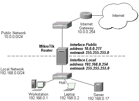
The IP addresses and routes of the MikroTik router are as follows:
[admin@MikroTik] > ip address print
Flags: X - disabled, I - invalid, D - dynamic
  #   ADDRESS            NETWORK         BROADCAST       INTERFACE
  0   10.0.0.217/24      10.0.0.0        10.0.0.255      Public
  1   192.168.0.254/24   192.168.0.0     192.168.0.255   Local
[admin@MikroTik] > ip route print
Flags: X - disabled, I - invalid, D - dynamic, J - rejected,
C - connect, S - static, R - rip, O - ospf, B - bgp
    #    DST-ADDRESS        G GATEWAY         DISTANCE INTERFACE
    0  S 0.0.0.0/0          r 10.0.0.254      1        Public
    1 DC 192.168.0.0/24     r 0.0.0.0         0        Local
    2 DC 10.0.0.0/24        r 0.0.0.0         0        Public
[admin@MikroTik] >
[admin@MikroTik] > ip firewall rule input
[admin@MikroTik] ip firewall rule input> add protocol=tcp tcp-option=non-syn-only \
\... connection-state=established comment="Allow established TCP connections"
[admin@MikroTik] ip firewall rule input> add protocol=udp comment="Allow UDP connections"
[admin@MikroTik] ip firewall rule input> add protocol=icmp comment="Allow ICMP messages"
[admin@MikroTik] ip firewall rule input> add src-addr=10.5.8.0/24 \
\... comment="Allow access from 'trusted' network 10.5.8.0/24"
[admin@MikroTik] ip firewall rule input> add action=reject log=yes \
\... comment="Reject and log everything else"
[admin@MikroTik] ip firewall rule input> print
Flags: X - disabled, I - invalid, D - dynamic
  0   ;;; Allow established TCP connections
      src-address=0.0.0.0/0:0-65535 in-interface=all
      dst-address=0.0.0.0/0:0-65535 out-interface=all protocol=tcp
      icmp-options=any:any tcp-options=non-syn-only
      connection-state=established flow="" connection="" content=""
      src-mac-address=00:00:00:00:00:00 limit-count=0 limit-burst=0
      limit-time=0s action=accept log=no

  1   ;;; Allow UDP connections
      src-address=0.0.0.0/0:0-65535 in-interface=all
      dst-address=0.0.0.0/0:0-65535 out-interface=all protocol=udp
      icmp-options=any:any tcp-options=any connection-state=any flow=""
      connection="" content="" src-mac-address=00:00:00:00:00:00 limit-count=0
      limit-burst=0 limit-time=0s action=accept log=no

  2   ;;; Allow ICMP messages
      src-address=0.0.0.0/0:0-65535 in-interface=all
      dst-address=0.0.0.0/0:0-65535 out-interface=all protocol=icmp
      icmp-options=any:any tcp-options=any connection-state=any flow=""
      connection="" content="" src-mac-address=00:00:00:00:00:00 limit-count=0
      limit-burst=0 limit-time=0s action=accept log=no

  3   ;;; Allow access from 'trusted' network 10.5.8.0/24 of ours
      src-address=10.5.8.0/24:0-65535 in-interface=all
      dst-address=0.0.0.0/0:0-65535 out-interface=all protocol=all
      icmp-options=any:any tcp-options=any connection-state=any flow=""
      connection="" content="" src-mac-address=00:00:00:00:00:00 limit-count=0
      limit-burst=0 limit-time=0s action=accept log=no

  4   ;;; Reject and log everything else
      src-address=0.0.0.0/0:0-65535 in-interface=all
      dst-address=0.0.0.0/0:0-65535 out-interface=all protocol=all
      icmp-options=any:any tcp-options=any connection-state=any flow=""
      connection="" content="" src-mac-address=00:00:00:00:00:00 limit-count=0
      limit-burst=0 limit-time=0s action=reject log=yes

[admin@MikroTik] ip firewall rule input>
Thus, the input chain will accept only allowed connections and reject and log everything else.
[admin@MikroTik] ip firewall> add name=customer
[admin@MikroTik] ip firewall> print
  # NAME                                                                 POLICY
  0 input                                                                accept
  1 forward                                                              accept
  2 output                                                               accept
  3 router                                                               none
  4 customer                                                             none
[admin@MikroTik] ip firewall> rule customer
[admin@MikroTik] ip firewall rule customer> add protocol tcp tcp-option non-syn-only \
\... connection-state=established comment="Allow established TCP connections"
[admin@MikroTik] ip firewall rule customer> add protocol udp \
\... comment="Allow UDP connections"
[admin@MikroTik] ip firewall rule customer> add protocol icmp \
\... comment="Allow ICMP messages"
[admin@MikroTik] ip firewall rule customer> add protocol tcp tcp-option syn-only \
\... dst-address 192.168.0.17/32:80 \
\... comment="Allow http connections to the server at 192.168.0.17"
[admin@MikroTik] ip firewall rule customer> add protocol tcp tcp-option syn \
\... dst-address 192.168.0.17/32:25 \
\... comment="Allow smtp connections to the server at 192.168.0.17"
[admin@MikroTik] ip firewall rule customer> add protocol tcp tcp-option syn \
\... src-port 20 dst-port 1024-65535 \
\... comment="Allow ftp data connections from servers on the Internet"
[admin@MikroTik] ip firewall rule customer> add action reject log yes \
\... comment="Reject and log everything else"
[admin@MikroTik] ip firewall rule customer> print
Flags: X - disabled, I - invalid
  0   ;;; Allow established TCP connections
      src-address=0.0.0.0/0:0-65535 in-interface=all
      dst-address=0.0.0.0/0:0-65535 out-interface=all protocol=tcp
      icmp-options=any:any tcp-options=non-syn-only
      connection-state=established flow="" connection="" content=""
      src-mac-address=00:00:00:00:00:00 limit-count=0 limit-burst=0
      limit-time=0s action=accept log=no

  1   ;;; Allow UDP connections
      src-address=0.0.0.0/0:0-65535 in-interface=all
      dst-address=0.0.0.0/0:0-65535 out-interface=all protocol=udp
      icmp-options=any:any tcp-options=any connection-state=any flow=""
      connection="" content="" src-mac-address=00:00:00:00:00:00 limit-count=0
      limit-burst=0 limit-time=0s action=accept log=no

  2   ;;; Allow ICMP messages
      src-address=0.0.0.0/0:0-65535 in-interface=all
      dst-address=0.0.0.0/0:0-65535 out-interface=all protocol=icmp
      icmp-options=any:any tcp-options=any connection-state=any flow=""
      connection="" content="" src-mac-address=00:00:00:00:00:00 limit-count=0
      limit-burst=0 limit-time=0s action=accept log=no

  3   ;;; Allow http connections to the server at 192.168.0.17
      src-address=0.0.0.0/0:0-65535 in-interface=all
      dst-address=192.168.0.17/32:80 out-interface=all protocol=tcp
      icmp-options=any:any tcp-options=syn-only connection-state=any flow=""
      connection="" content="" src-mac-address=00:00:00:00:00:00 limit-count=0
      limit-burst=0 limit-time=0s action=accept log=no

  4   ;;; Allow smtp connections to the server at 192.168.0.17
      src-address=0.0.0.0/0:0-65535 in-interface=all
      dst-address=192.168.0.17/32:25 out-interface=all protocol=tcp
      icmp-options=any:any tcp-options=syn-only connection-state=any flow=""
      connection="" content="" src-mac-address=00:00:00:00:00:00 limit-count=0
      limit-burst=0 limit-time=0s action=accept log=no

  5   ;;; Allow ftp data connections from servers on the Internet
      src-address=0.0.0.0/0:20 in-interface=all
      dst-address=0.0.0.0/0:1024-65535 out-interface=all protocol=tcp
      icmp-options=any:any tcp-options=syn-only connection-state=any flow=""
      connection="" content="" src-mac-address=00:00:00:00:00:00 limit-count=0
      limit-burst=0 limit-time=0s action=accept log=no

  6   ;;; Reject and log everything else
      src-address=0.0.0.0/0:0-65535 in-interface=all
      dst-address=0.0.0.0/0:0-65535 out-interface=all protocol=all
      icmp-options=any:any tcp-options=any connection-state=any flow=""
      connection="" content="" src-mac-address=00:00:00:00:00:00 limit-count=0
      limit-burst=0 limit-time=0s action=reject log=yes

[admin@MikroTik] ip firewall rule customer>
Note about the rule #5: active ftp data connections are made from the server's port 20 to the client's tcp port above 1024.
All we have to do now is to put rules in the forward chain, that match the IP addresses of the customer's hosts on the Local interface and jump to the customer chain:
[admin@MikroTik] ip firewall rule forward> add out-interface=Local action=jump \
\... jump-target=customer
[admin@MikroTik] ip firewall rule forward> print
Flags: X - disabled, I - invalid
  0   src-address=0.0.0.0/0:0-65535 in-interface=all
      dst-address=0.0.0.0/0:0-65535 out-interface=Local protocol=all
      icmp-options=any:any tcp-options=any connection-state=any flow=""
      connection="" content="" src-mac-address=00:00:00:00:00:00 limit-count=0
      limit-burst=0 limit-time=0s action=jump jump-target=customer log=no

[admin@MikroTik] ip firewall rule forward>
Thus, everything that passes the router and leaves the Local interface (destination of the customer's network) will be processed against the firewall rules of the customer chain.
[admin@MikroTik] ip firewall rule forward> add protocol icmp out-interface Public \
\... comment="Allow ICMP ping packets"
[admin@MikroTik] ip firewall rule forward> add src-address 192.168.0.17/32 out-interface \
\... Public comment="Allow outgoing connections form the server at 192.168.0.17"
[admin@MikroTik] ip firewall rule forward> add action reject out-interface Public log yes \
\... comment="Reject and log everything else"
[admin@MikroTik] ip firewall rule forward> print
Flags: X - disabled, I - invalid
  0   src-address=0.0.0.0/0:0-65535 in-interface=all
      dst-address=0.0.0.0/0:0-65535 out-interface=Local protocol=all
      icmp-options=any:any tcp-options=any connection-state=any flow=""
      connection="" content="" src-mac-address=00:00:00:00:00:00 limit-count=0
      limit-burst=0 limit-time=0s action=jump jump-target=customer log=no

  1   ;;; Allow ICMP ping packets
      src-address=0.0.0.0/0:0-65535 in-interface=all
      dst-address=0.0.0.0/0:0-65535 out-interface=Public protocol=icmp
      icmp-options=any:any tcp-options=any connection-state=any flow=""
      connection="" content="" src-mac-address=00:00:00:00:00:00 limit-count=0
      limit-burst=0 limit-time=0s action=accept log=no

  2   ;;; Allow outgoing connections form the server at 192.168.0.17
      src-address=192.168.0.17/32:0-65535 in-interface=all
      dst-address=0.0.0.0/0:0-65535 out-interface=Public protocol=all
      icmp-options=any:any tcp-options=any connection-state=any flow=""
      connection="" content="" src-mac-address=00:00:00:00:00:00 limit-count=0
      limit-burst=0 limit-time=0s action=accept log=no

  3   ;;; Reject and log everything else
      src-address=0.0.0.0/0:0-65535 in-interface=all
      dst-address=0.0.0.0/0:0-65535 out-interface=Public protocol=all
      icmp-options=any:any tcp-options=any connection-state=any flow=""
      connection="" content="" src-mac-address=00:00:00:00:00:00 limit-count=0
      limit-burst=0 limit-time=0s action=reject log=yes

[admin@MikroTik] ip firewall rule forward>
To use masquerading, a source NAT rule with action 'masquerade' should be added to the firewall configuration:
[admin@MikroTik] ip firewall src-nat> add action=masquerade out-interface=Public
[admin@MikroTik] ip firewall src-nat> print
Flags: X - disabled, I - invalid
  0   src-address=0.0.0.0/0:0-65535 dst-address=0.0.0.0/0:0-65535
      out-interface=Public protocol=all icmp-options=any:any flow=""
      connection="" content="" limit-count=0 limit-burst=0 limit-time=0s
      action=masquerade to-src-address=0.0.0.0 to-src-port=0-65535

[admin@MikroTik] ip firewall src-nat>
All outgoing connections from the network 192.168.0.0/24 will have source address 10.0.0.217 of the router and source port above 1024. No access from the Internet will be possible to the Local addresses. If you want to allow connections to the server on the local network, you should use destination Network Address Translation (NAT).
Assume you need to configure the MikroTik router for the following network setup, where the server is located in the private network area:
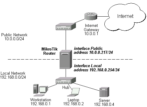
The server has address 192.168.0.4, and we are running web server on it that listens to the TCP port 80. We want to make it accessible from the Internet at address:port 10.0.0.217:80. This can be done by means of destination Network Address Translation (NAT) at the MikroTik Router. The Public address:port 10.0.0.217:80 will be translated to the Local address:port 192.168.0.4:80. One destination NAT rule is required for translating the destination address and port:
[admin@MikroTik] ip firewall dst-nat> add action=nat protocol=tcp \
\... dst-address=10.0.0.217/32:80 to-dst-address=192.168.0.4
[admin@MikroTik] ip firewall dst-nat> print
Flags: X - disabled, I - invalid
  0   src-address=0.0.0.0/0:0-65535 in-interface=all
      dst-address=10.0.0.217/32:80 protocol=tcp icmp-options=any:any flow=""
      connection="" content="" src-mac-address=00:00:00:00:00:00 limit-count=0
      limit-burst=0 limit-time=0s action=nat to-dst-address=192.168.0.4
      to-dst-port=0-65535

[admin@MikroTik] ip firewall dst-nat>
Read about connection tracking at
http://www.cs.princeton.edu/~jns/security/iptables/iptables_conntrack.html
Read more about NAT in RFC2663