The document consists of 16 main parts. Parts can be divided further into sections. Each section (or a part if it doesn't consist of sections) of this document is divided into three subsections. In the first subsection, management from the Java Console is described. Management from the Console is described in the second subsection. The third subsection is devoted to description of the parameters. However some sections are not divided if it is not necessary.
The current manual version is being updated to a new format. Some sections of this manual are in our old format and some in the newer format. It is expected that all sections will be updated by June.
In this publication, the following conventions are used:
| to the contents |
Working with Interfaces
Adding Addresses
Configuring the Default Route
Testing the Network Connectivity
Application Example with Masquerading
Application Example with Bandwidth Management
Accessing the Router Remotely using Web Browser and Java Console
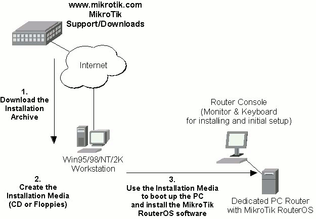
The download and installation process of the MikroTik RouterOS is described in the following diagram:
1. Download the basic installation archive file.
Depending on the desired media to be used for installing the MikroTik RouterOS please chose one of the following archive types for downloading:2. Create the installation media
Use the appropriate installation archive to create the Installation CD or floppies.3. Install the MikroTik RouterOS software.
Your dedicated PC router hardware should have:After successful installation please remove the installation media from your CD or floppy disk drive and hit 'Enter' to reboot the router. While the router will be starting up for the first time you will be given a Software ID for your installation and asked to supply a valid software license key (Software Key) for it. Write down the Software ID. You will need it to obtain the Software License after logging on to the MikroTik Account Server.
If you need extra time to obtain the Software License Key, you may want to power off the router. Press Ctrl-Alt-Del keys to properly shut down and reboot the router. Power the router off while the BIOS is doing memory check.
The MikroTik RouterOS Softare licensing process is described in the following diagram:
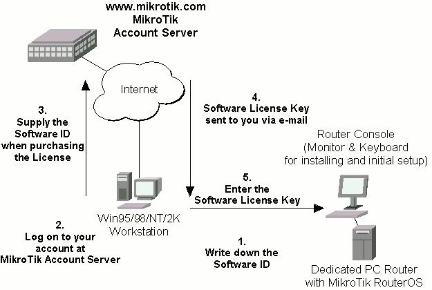
After installing the router and starting it up for the first time you will be given a Softwarte ID.
If you do not have an account at www.mikrotik.com, just press the 'New' button to create your account. You will be presented with the Account Sign-Up Form where you chose your account name and fill in the required information.
Software ID: 5T4V-IUT
Software key: 4N7X-UZ8-6SP
After entering the correct Software License Key you will be presented with the MikroTik Router's login prompt. Use 'admin' and no password (hit 'Enter') for logging on to the router, for example:
MikroTik v2.3.8 (build 9)
mikrotik login: admin
Password:
The password can be changed with the '/password' command.
After logging on to the router you will be presented with the MikroTik RouterOS Welcome Screen and command prompt, for example:
  MMM      MMM       KKK                          TTTTTTTTTTT      KKK
  MMMM    MMMM       KKK                          TTTTTTTTTTT      KKK
  MMM MMMM MMM  III  KKK  KKK  RRRRRR     OOOOOO      TTT     III  KKK  KKK
  MMM  MM  MMM  III  KKKKK     RRR  RRR  OOO  OOO     TTT     III  KKKKK
  MMM      MMM  III  KKK KKK   RRRRRR    OOO  OOO     TTT     III  KKK KKK
  MMM      MMM  III  KKK  KKK  RRR  RRR   OOOOOO      TTT     III  KKK  KKK

  MikroTik RouterOS V2.3 (c) 1999-2001       http://mikrotik.com/

command [Enter] Executes the command

[?]             Gives the list of available commands
command [?]     Gives help on the command and list of arguments
command arg [?] Gives help on the command's argument

[Tab]           Completes the command/word. If the input is ambiguous,
                a second [Tab] gives possible options

/               Move up to base level
..              Move up one level
/command        Use command at the base level

Tip: Read the manual.

[mikrotik]>
The command prompt shows the identity name of the router and the current menu level, for example:
[mikrotik]>                      Base level menu
[mikrotik]> driver               Enter 'driver' to move to the driver level menu
[mikrotik] driver> /             Enter '/' to move to the base level menu from any level
[mikrotik]> interface            Enter 'interface' to move to the interface level menu
[mikrotik] interface> /ip        Enter '/ip' to move to the IP level menu from any level
[mikrotik] ip>
A command or an argument does not need to be completed, if it is not ambiguous. For example, instead of typing 'interface' you can type just 'in' or 'int'. To complete a command use 'Tab' key. Use '?' to see the list of possible commands at a given menu level.
Before configuring the IP addresses and routes please check the '/interface' menu to see the list of available interfaces. If you have PCI Ethernet cards installed in the router, it is most likely that the device drivers have been loaded for them automatically, and the relevant interfaces appear on the '/interface print' list, for example:
[mikrotik] interface> print
  # NAME                                                   TYPE        MTU
( 0)ether0                                                 ether       1500
( 1)ether1                                                 ether       1500
[mikrotik] interface>
The device drivers for NE2000 compatible ISA cards need to be loaded using the 'load' command under the /drivers menu. For example, to load the driver for a card with IO address 0x300 and IRQ 5, it is enough to issue the command:
[mikrotik] driver> load ne2k-isa io 0x300
[mikrotik] driver>
The interfaces need to be enabled if you want to use them for communications. Use the '/interface enable name' command to enable the interface with a given name. Enabled interfaces do not have the numbers enclosed in braces. For example:
[mikrotik] interface> enable 0
[mikrotik] interface> enable ether1
[mikrotik] interface> print
  # NAME                                                   TYPE        MTU
  0 ether0                                                 ether       1500
  1 ether1                                                 ether       1500
[mikrotik] interface>
You can use the number or the name of the interface in the 'enable' command.
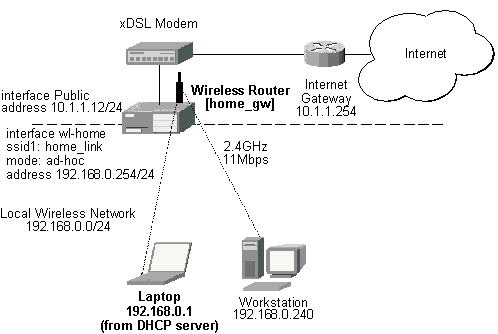
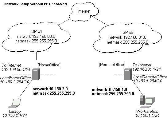
Assume you need to configure the MikroTik router for the following network setup:
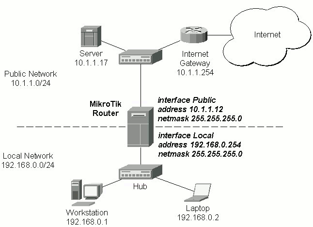
Please note that the addresses assigned to different interfaces of the router should belong to different networks. In the current example we use two networks:
The addresses can be added and viewed using the following commands:
[mikrotik] ip address> add address 192.168.0.254/24 interface ether1
[mikrotik] ip address> add address 10.1.1.12/24 interface ether0
[mikrotik] ip address> print
  # ADDRESS         NETMASK         NETWORK         BROADCAST       INTERFACE
  0 192.168.0.254   255.255.255.0   192.168.0.254   192.168.0.255   ether1
  1 10.1.1.12       255.255.255.0   10.1.1.12       10.1.1.255      ether0
[mikrotik] ip address>
Here, the network mask has been specified in the value of the address argument. Alternatively, the argument 'netmask' could have been used with the value '255.255.255.0'. The network and broadcast addresses were not specified in the input since they could been calculated automatically.
You can see two dynamic (D) kernel (K) routes, which have been added automatically when the addresses were added:
[mikrotik] ip address> /ip route print
  # DST-ADDRESS     NETMASK         GATEWAY         PREF-ADDRESS    INTERFACE
  0 192.168.0.0     255.255.255.0   0.0.0.0         192.168.0.254   ether1     D K
  1 10.1.1.0        255.255.255.0   0.0.0.0         10.1.1.12       ether0     D K
[mikrotik] ip address>
These routes show, that IP packets with destination to 10.1.1.0/24 would be sent through the interface ether0, whereas IP packets with destination to 192.168.0.0/24 would be sent through the interface ether1. However, you need to specify where the router should forward packets, which have destination other than networks connected directly to the router. This is done by adding the default route (destination 0.0.0.0, netmask 0.0.0.0). In this case it is the ISP's gateway 10.1.1.254, which can be reached through the interface ether0:
[mikrotik] ip address> /ip route add gateway 10.1.1.254 interface test
[mikrotik] ip address> /ip route print
  # DST-ADDRESS     NETMASK         GATEWAY         PREF-ADDRESS    INTERFACE
  0 10.0.0.0        255.255.255.0   0.0.0.0         10.0.0.222      developers D K
[mikrotik] ip address> /ip route print
  # DST-ADDRESS     NETMASK         GATEWAY         PREF-ADDRESS    INTERFACE
  0 192.168.0.0     255.255.255.0   0.0.0.0         192.168.0.254   ether1     D K
  1 10.1.1.0        255.255.255.0   0.0.0.0         10.1.1.12       ether0     D K
  2 0.0.0.0         0.0.0.0         10.0.0.1        0.0.0.0         ether0
[mikrotik] ip address>
Here, the default route is listed under #2. Note, that you should not have two routes to the same destination, i.e., destination-address/netmask! It applies to the default routes as well. Situation with two routes to the same destination is confusing.
If you have added an unwanted static route accidentally, use the 'remove' command to delete the unneeded one. Do not remove the kernel (K) or dynamic (D) routes! They are added automatically and should not be deleted 'by hand'. If you happen to, then reboot the router, the route will show up again.
From now on, the '/ping' command can be used to test the network connectivity on both interfaces. You can reach any host on both connected networks from the router:
[mikrotik] ip address> /ping 10.1.1.17
10.1.1.17 pong: ttl=255 time<1 ms
10.1.1.17 pong: ttl=255 time<1 ms
10.1.1.17 pong: ttl=255 time<1 ms
ping interrupted
3 packets transmitted, 3 packets received, 0% packet loss
round-trip min/avg/max = 0/0.0/0 ms
interrupted
[mikrotik] ip address> /ping 192.168.0.1
192.168.0.1 pong: ttl=255 time<1 ms
192.168.0.1 pong: ttl=255 time<1 ms
192.168.0.1 pong: ttl=255 time<1 ms
ping interrupted
3 packets transmitted, 3 packets received, 0% packet loss
round-trip min/avg/max = 0/0.0/0 ms
interrupted
[mikrotik] ip address>
The workstation and the laptop can reach (ping) the router at its local address 192.168.0.254, whereas the server can reach the router at its local address 10.1.1.12 The router's address 192.168.0.254 should be specified as the default gateway in the TCP/IP configuration of both the workstation and the laptop. Then you should be able to ping the router's address 10.1.1.12 which is on the ISP's network:
C:\>ping 10.1.1.12
Pinging 10.1.1.12 with 32 bytes of data:
Reply from 10.1.1.12: bytes=32 time<10ms TTL=255
Reply from 10.1.1.12: bytes=32 time<10ms TTL=255
Reply from 10.1.1.12: bytes=32 time<10ms TTL=255
C:\>
You cannot ping the workstation and laptop from the server, unless you do the following:
Next will be discussed situation with 'hiding' the private LAN 192.168.0.0/24 'behind' one address 10.1.1.12 given to you by the ISP.
If you want to 'hide' the private private LAN 192.168.0.0/24 'behind' one address 10.1.1.12 given to you by the ISP, you should use the masquerading function of the MikroTik router. Masquerading is useful, if you want to access the ISP's network and the Internet appearing as all requests coming from the host 10.1.1.12 of the ISP's network. The masquerading will change the source IP address and port of the packets originated from the network 192.168.0.0/24 to the address 10.1.1.12 of the router, when the packet is routed through it.
A firewall rule with action 'masq' should be added to the forward chain of the router's firewall configuration:
[mikrotik] ip firewall rule> add forward action masq interface ether0
[mikrotik] ip firewall rule> print forward
0   action: masq protocol: all src-address: 0.0.0.0 src-netmask: 0.0.0.0
    src-ports: 0-65535 dst-address: 0.0.0.0 dst-netmask: 0.0.0.0
    dst-ports: 0-65535 interface: ether0 log: no
[mikrotik] ip firewall rule>
More detailed information about using the masquerading can be found in the IP Firewalling section of the MikroTik RouterOS Manual.
Assume you want to limit the bandwidth to 128kbps on downloads and 64kbps on uploads for all hosts on the LAN. Bandwidth limitation is done by applying queues for outgoing interfaces regarding the traffic flow. It is enough to add two queues at the MikroTik router:
[mikrotik] ip queue>add interface ether1 queue red limit-at 128000 max-burst 0 bounded yes
[mikrotik] ip queue>add interface ether0 queue red limit-at 64000 max-burst 0 bounded yes
[mikrotik] ip queue> print
0   src-address: 0.0.0.0/0:0-65535 dst-address: 0.0.0.0/0:0-65535 interface: ether1
    protocol: 0 queue: red limit-at: 128000 max-burst: 0 bounded: yes priority: 8
    weight: 1 allot: 1538 red-limit: 60 red-min-threshold: 10
    red-max-threshold: 50 red-burst: 20
1   src-address: 0.0.0.0/0:0-65535 dst-address: 0.0.0.0/0:0-65535 interface: ether0
    protocol: 0 queue: red limit-at: 64000 max-burst: 0 bounded: yes priority: 8
    weight: 1 allot: 1538 red-limit: 60 red-min-threshold: 10
    red-max-threshold: 50 red-burst: 20
[mikrotik] ip queue>
Leave all other parameters as set by default. The limit is approximately 128kbps going to the LAN and 64kbps leaving the client's LAN. No burst of the packets is allowed. Please note, that each queue has been added for the outgoing interface regarding the traffic flow.
More detailed information about using the bandwidth management can be found in the Bandwidth Management and Queuing section of the MikroTik RouterOS Manual.
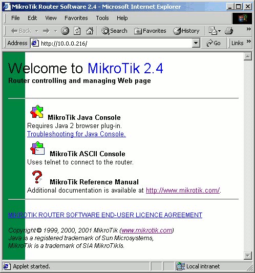
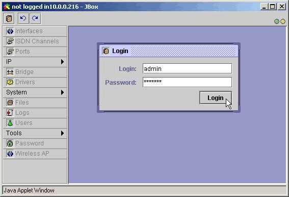
By clicking on the Java Console icon you can open the Java console with the login window. Use the username and password to log on to the router, for example:
After logging on to the router you can work with the MikroTik router's configuration through the Java console and perform the same tasks as using the regular console:
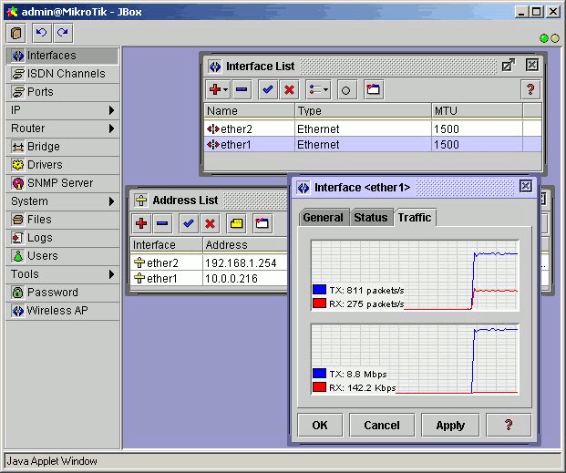
You can use the menu bar to navigate through the router's configuration menus, open configuration windows. By double clicking on some list items in the windows you can open configuration windows for the specific items, and so on. Please consult the MikroTik RouterOS Manual for more detailed description of using the Java console.
The basic installation comes with only the "system" package and few other packages. This includes basic IP routing and router administration. To have additional features such as IP Telephony, OSPF, wireless, and so on, you will need to download additional software packages. Please consult the MikroTik RouterOS Software Package Installation and Upgrading Manual for more detailed information about installing additional software packages.
| to the contents |
MikroTik Java Console requires Java 2 browser plug-in. This may be downloaded from the "Download" page at mikrotik.com or www.sun.com.
In the Web Browser open the page with the address http://<IPAddressOfTheRouter>. Then start the applet.
When you type your login name and password you are logged in the router via Java Console.
All operations are performed via the main menu that is situated on the left of the main window. It consists of twelve items. If a menu item has an arrow sign then it contains submenu. Each of menu item is described in the User Manual in the corresponding chapters, excluding menu item "Help". The table below describes the correlation.
| Menu Item | Chapter Name |
|---|---|
| Interfaces | Network Interface Management |
| IP | Internet Protocol Management |
| Router | Advanced Routing Management |
| Bridge | Bridge Configuration |
| Drivers | Device Drivers Management |
| SNMP Server | SNMP Service Configuration |
| System | System Configuration |
| Logs | System Configuration |
| Users | System Configuration |
| Tools | Tools |
| Password | System Configuration |
Here are the most common actions that you perform on the entries:
| Action | Description |
|---|---|
| Open | To open the required window simply click on the corresponding menu item. |
| Add | To add a new entry you should click on the icon in the corresponding window. |
| Remove | To remove an existing entry click on the icon. |
| Edit | Click twice on the icon on the left of each line. |
| Enable | To enable interface, address etc. click the icon. |
| Disable | To disable interface, address etc. click the icon. |
| Comment | To save a comment an entry click the icon. |
| Refresh | Click on the icon in the corresponding window. |
| Undo | Click on the icon above the main menu. |
| Redo | Click on the icon above the main menu. |
| Logout | Click on the icon above the main menu. |
Main Menu
When you log into the router via console or telnet you get a base level prompt. As it is in Java almost every command has the corresponding chapter in the Manual. In the table below base level commands are described:
| Command Name | Description | Chapter in the Manual |
|---|---|---|
| ping | Send ICMP Echo packets | Tools |
| tool | System tools | Tools |
| user | User management | System Configuration/ User Management |
| log | View system logs | System Configuration/ System Logs Management |
| quit | Quit console | |
| setup | Do basic setup of the system | Basic System Setup |
| password | Change user password | System Configuration/ Change Password |
| undo | Undo previous action | |
| redo | Redo previous action | |
| export | Export router settings | User Interconnection Description |
| interface | Interface configuration | Network Interface Management |
| driver | Driver management | Device Driver Management |
| system | System configuration | System Configuration |
| bridge | Bridge configuration | Bridge Configuration |
| snmp-server | SNMP server configuration | SMNP Service Configuration |
| terminal | Set terminal type | Terminal Setup and Basic System Setup |
| ip | IPv4 specific settings | Internet Protocol Management |
| router | Routing settings | Advanced Routing Management |
The table below describes how you can execute commands, move through the levels in the console, etc.
| Command | Action |
|---|---|
| command [Enter] | Execute the command |
| [?] | Show the list of all available commands |
| command [?] | Display help on the command and the list of arguments |
| command argument [?] | Display help on the command's argument |
| [Tab] | Complete the command/word. If the input is ambiguous, a second [Tab] gives possible options |
| / | Move up to the base level |
| /command | Execute the base level command |
| .. | Move up one level |
| "" | Enter an empty string |
| "word1 word2" | Enter 2 words that contain a space |
You can abbreviate names of levels, commands and arguments.
The console allows configuration of the router settings using text commands. The command structure is similar to the Unix shell. Since there's a whole lot of available commands, they're split into hierarchy. For example, all commands that work with routes start with "ip route":
[drax]> ip route print
|
#
|
DST-ADDRESS | NETMASK | GATEWAY | PREF-ADDRESS | INTE... |
|
0
|
0.0.0.0
|
0.0.0.0
|
10.0.0.1
|
0.0.0.0
|
ether1 D
|
|
1
|
10.0.0.0
|
255.255.255.0
|
0.0.0.0
|
10.0.0.65
|
ether1 D K
|
[drax]> ip route set 1 netmask 255.255.0.0
[drax]> ip route print
|
#
|
DST-ADDRESS | NETMASK | GATEWAY | PREF-ADDRESS | INTE... |
|
0
|
0.0.0.0
|
0.0.0.0
|
10.0.0.1
|
0.0.0.0
|
ether1 D
|
|
1
|
10.0.0.0
|
255.255.0.0
|
0.0.0.0
|
10.0.0.65
|
ether1 D K
|
Instead of typing "ip route" before each command, "ip route" can be typed once to "change into" that particular branch of command hierarchy. Thus, the example above could also be executed like this:
[drax]> ip route
[drax] ip route> print
|
#
|
DST-ADDRESS | NETMASK | GATEWAY | PREF-ADDRESS | INTE... |
|
0
|
0.0.0.0
|
0.0.0.0
|
10.0.0.1
|
0.0.0.0
|
ether1 D
|
|
1
|
10.0.0.0
|
255.255.255.0
|
0.0.0.0
|
10.0.0.65
|
ether1 D K
|
[drax] ip route> set 1 netmask 255.255.0.0
[drax]> ip route print
|
#
|
DST-ADDRESS | NETMASK | GATEWAY | PREF-ADDRESS | INTE... |
|
0
|
0.0.0.0
|
0.0.0.0
|
10.0.0.1
|
0.0.0.0
|
ether1 D
|
|
1
|
10.0.0.0
|
255.255.0.0
|
0.0.0.0
|
10.0.0.65
|
ether1 D K
|
Notice that prompt changes to show where in the command hierarchy you are located at the moment. To change to top level, type "/"
[drax] ip route> /
[drax]>
To move up one command level, type ".."
[drax] ip route> ..
[drax] ip>
You can also use "/" and ".." to execute commands from other levels without changing the current level:
[drax] ip route> /ping 10.0.0.10
timeout: ping reply not recieved after 1000 mss
timeout: ping reply not recieved after 1000 mss
ping interrupted 2 packets transmitted, 0 packets received, 100% packet loss
interrupted
Or alternatively, to go back to the base level you could use the ".." twice:
[drax] ip route> .. .. ping 10.0.0.10
10.0.0.10 pong: ttl=128 time=2 ms
10.0.0.10 pong: ttl=128 time=1 ms
ping interrupted 2 packets transmitted, 2 packets received, 0% packet loss
round-trip min/avg/max = 1/1.5/2 ms
interrupted
[drax] ip route>
- Lists -
Many of the command levels operate with arrays of items: interfaces, routes, users etc. Such arrays are displayed in similar looking lists. All items in the list have an item number followed by it's parameter values. For example:
[drax]> interface print
# NAME STATE TYPE MTU
| # |
NAME
|
STATE
|
TYPE
|
MTU
|
| 0 |
ether5
|
up
|
ethernet
|
1500
|
| 1 |
ether1
|
up
|
ethernet
|
1500
|
To change parameters of an item (interface in this particular case), you have to specify it's number:
[drax]> interface set 1 mtu 1234
[drax]> interface print
| # |
NAME
|
STATE
|
TYPE
|
MTU
|
| 0 |
ether5
|
up
|
ethernet
|
1500
|
| 1 |
ether1
|
up
|
ethernet
|
1234
|
Numbers are assigned by "print" command and are not constant - it is possible that two successive "print" commands will order items differently. Thus, you must use the print command before any other command that works with list items, to assign numbers.
Note Although numbers can change each time you use the "print" command, they don't change between these uses. Once assigned, they will remain the same until you quit the console or until the next "print" command. Also, numbers are assigned separately for every item list, so "ip address print" won't change numbers for interface list.
Let's assume "ip address print" hasn't been executed already. In this case:
[drax]> ip address set 123 netmask
255.255.0.0
Error: number : (no numbers assigned)
To understand better how do item numbers work, you can play with "from" argument of "print" commands:
[drax]> interface print from 1
| # |
NAME
|
STATE
|
TYPE
|
MTU
|
| 1 |
ether1
|
up
|
ethernet
|
1500
|
The "from" argument specifies what items to show. Numbers are assigned by every "print" command, thus, after executing command above there will be only one item accessible by number - interface "ether1" by number 0.
- Item names -
Some lists have items that have specific names assigned to each. Examples are "interface" or "user" levels. There you can use item names instead of numbers:
[drax]> interface set ether1 mtu 1234
You don't have to use the "print" command before accessing items by name - as opposed to numbers, names are not assigned by the console internally, but are one of the items' parameters. Thus, they won't change on their own (But there are all kinds of obscure situations possible when several users are changing router configuration at the same time). Generally, item names are more "stable" than numbers, and also more informative, so you should prefer them ver numbers when writing console scritps. Also, <tab> completions work on item names, making them easy to type.
- Quick typing -
There are two features in router console that help entering commands a lot quicker and easier - tab key completions and abbreviations of command names. Completions work similarly to the bash shell in UNIX. If you press the tab key after part of word, console tries to find command in current context that begins with this word. If there's only one match, it is automatically appended, followed by space character:
/inte<tab>_ becomes /interface _
(where "_" is cursor position)
If there's more than one match, but they all have a common beginning which is longer that what you've typed, then the word is completed to this common part, and no space is appended:
/interface set e<tab>_ becomes
/interface set ether_
(because "e" matches both "ether5" and "ether1" in this example)
If you've typed just the common part, pressing the tab key once has no effect. However, pressing it second time shows all possible completions in compact form:
[drax]> /interface set e<tab>_
[drax]> /interface set ether<tab>_
[drax]> /interface set ether<tab> ether1 ether5
[drax]> /interface set ether_
The tab key can be used almost in any context where the console might have a clue about possible values - command names, argument names, arguments that have only several possible values (like names of items in some lists or name of protocol in firewall and NAT rules). You can't complete numbers, IP addresses and similar values.
Another way to press less keys while typing is to abbreviate command and argument names. You can type only beginning of command name, and if it is not ambiguous console will accept it as a full name:
[drax]> ip f s r 1 equals to [drax]> ip firewall static-nat remove 1
[drax]> pi 10.1 c 3 s 100 equals to [drax]> ping 10.0.0.1 count 3 size 100
Note ".." can be shortened to ".", because no other words in command levels begin with dot.
- Help -
The console has a built-in help, which can be accessed by typing '?'. General rule is that help shows what you can type in position where the '?' was pressed (similarly to pressing tab key twice, but in verbose form and with explanations).
- Internal item numbers -
Items can also be addressed by their internal numbers. These numbers are generated by console for scripting purposes and, as the name implies, are used internally. Although you can see them if you print return values of some commands (internal numbers look like hex number preceded by '*' - for example "*100A"), there's no reason for you to type them in manually. Use of invalid internal numbers can result in severe injury of your router configuration.
- Multiple items -
You can specify multiple items as targets of some commands. Almost everywhere, where you can write the number of items, you can also write a list of numbers:
[drax]> interface print
| # |
NAME
|
STATE
|
TYPE
|
MTU
|
| 0 |
ether5
|
up
|
ethernet
|
1500
|
| 1 |
ether1
|
up
|
ethernet
|
1234
|
| # |
NAME
|
STATE
|
TYPE
|
MTU
|
| 0 |
ether5
|
up
|
ethernet
|
1600
|
| 1 |
ether1
|
up
|
ethernet
|
1600
|
This is handy when you want to perform same action on several items, or do a selective export. However, this feature becomes really useful when combined with scripting.
- Return values -
The router console has limited scripting capability. Syntax is simple and similar to TCL. There's a new command "find" added to many of the command levels for scripting use. This command doesn't print anything on screen. Instead, it creates a return value that contains internal numbers of items that match parameters of the "find" command. This return value can be used in another command, by placing "find" in square brackets:
[drax]> interface
[drax] interface> print from [find name ether5]
| # |
NAME
|
STATE
|
TYPE
|
MTU
|
| 0 |
ether5
|
up
|
ethernet
|
1600
|
| # |
NAME
|
STATE
|
TYPE
|
MTU
|
| 0 |
ether5
|
up
|
ethernet
|
1001
|
If you don't give "find" any arguments, it returns internal numbers of all items:
[drax] interface> set [find] mtu 1500
[drax] interface> print
| # |
NAME
|
STATE
|
TYPE
|
MTU
|
| 0 |
ether5
|
up
|
ethernet
|
1500
|
| 1 |
ether1
|
up
|
ethernet
|
1500
|
You can see the return value of "find" command (and other router commands) using ":put" command:
[drax] interface> :put [find]
*10002 *10001
These are internal numbers of all router interfaces. Also, there's a trailing space after last number, so you can concatenate results of several "find" commands:
[drax] interface> print from [find][find]
| # |
NAME
|
STATE
|
TYPE
|
MTU
|
| 0 |
ether5
|
up
|
ethernet
|
1500
|
| 1 |
ether1
|
up
|
ethernet
|
1500
|
| 3 |
ether5
|
up
|
ethernet
|
1500
|
| 4 |
ether1
|
up
|
ethernet
|
1500
|
- Time Setting -
In the console time can be set in various ways. If it is just a number, then it is in seconds. You can also enter the following values:
| "d", "da", "day", "days" - 86400 seconds (1 day) |
| "h", "ho" ... "hours" - 3600 seconds (1 hour) |
| "m", "mi", "min" - 60 seconds (1 minute) |
| "s" - 1 seconds (1 second) |
| "ms" - 1 millisecond |
If the is no number before the letters, it will be one unit. You also can use decimal numbers. Multiple time intervals can be written consequently - they will be summarized.
- Variables -
The console has variables that can store string values. Assigning such a variable is done by ":set" command:
[drax]> :set var1 J.Random.String
If the value is assigned to a non-existing variable, it's created, otherwise current value is replaced. To access the value of variable, you have to type "$" followed by the name of the variable, and it will be replaced by the value of the variable:
[drax]> :put $var1
J.Random.String
[drax]> :put $var1-$var1-yo-ho-ho-$var1
J.Random.String-J.Random.String-yo-ho-ho-
J.Random.String
- Magic Variables -
There are two magic variables in the console. "_" (underscore) has the last valid command entered.
[drax]> /system clock print
jun/16/2000 17:06:57
[drax]> :put $_
/system clock print
[drax]> :put $_
:put $_
The second magic variable is the "^" (caret). It contains the return value of the last executed command. Note that all commands return values (even if they're empty strings), so if you want to use the return value of some command (say, "find") several times, you have to assign it to normal variable. In the console, "^" is used to export some items:
[drax]> ip firewall static-nat
[drax] ip firewall static-nat> print
|
(0)
|
;;; blah-blah |
| ;;; yadda-yadda | |
| src-address: 0.0.0.0 src-netmask: 0.0.0.0 src-port: 0-65535 | |
| dst-address: 0.0.0.0 dst-netmask: 0.0.0.0 dst-port: 0-65535 interface: all | |
| translate: no direction: in protocol: all to-src-address: 0.0.0.0 | |
| to-dst-address: 0.0.0.0 to-src-netmask: 0.0.0.0 to-dst-netmask: 0.0.0.0 | |
| to-src-port: 0 to-dst-port: 0 |
[drax] ip firewall static-nat> export
/ip firewall static-nat
add interface all src-address 0.0.0.0 src-netmask
0.0.0.0 \
dst-address 0.0.0.0 dst-netmask 0.0.0.0 protocol
all \
src-port 0-65535 dst-port 0-65535 to-src-address
0.0.0.0 \
to-dst-address 0.0.0.0 to-src-netmask 0.0.0.0 \
to-dst-netmask 0.0.0.0 to-src-port 0 to-dst-port 0
translate no \ direction in
comment $^ blah-blah\nyadda-yadda
disable $^
[drax] ip firewall static-nat>
Here, "add" returns internal number of item the it has added, and "comment" command returns list of internal numbers of items it received as the first argument. Thus "comment $^" will add comment to the item created by "add", and "disable $^" will disable this item.
- General layout of command levels -
There are two different kinds of command levels. First, there are levels that allow you to work with lists of similar items - routes, interfaces, users and the like. Second, there are levels that allow you to change some general parameters - time, bridge settings etc.
Most command groups have some or all of these commands:
print
set
remove
add
find
export
enable
disable
comment
These commands have similar behaviour in all hierarchy.
- print -
The "print" command shows all information that's accessible from particular command level. Thus, "/system time print" shows system time, "/ip route print" shows all routes etc. If there's a list of items in this level and they are not read-only, i.e. you can change/remove them (example of read-only item list is "/system history", which shows history of executed actions), then "print" command also assigns numbers that are used by all commands that operate on items in this list. Thus, "print" usually must be executed before any other commands in the same command level.
If there's list of items then "print" usually can have a "from" argument. The "from" argument accepts space separated list of item numbers, names (if items have them). and internal numbers. The action (printing) is performed on all items in this list in the same order in which they're given.
- set -
The "set" command allows you to change values of general parameters or item parameters. The "set" command has arguments with names corresponding to values you can change. Use "?" or double tab to see list of all arguments. If there is list of items in this command level, then set has one unnamed argument that accepts the number of item (or list of numbers) you wish to set up. Values for unnamed arguments must follow right after the name of the command, and their order can't be changed. Example: in firewall rules, the "set" command has two unnamed arguments - first is the name of chain and second is the number of rule in this chain. "set" returns internal numbers of items it has set up.
- remove -
"remove" has one unnamed argument which contains number(s) of item(s) to remove.
- add -
"add" usually has the same arguments as "set", minus the unnamed number argument. It adds new item with values you've specified, usually to the end of list (in places where order is relevant). There are some values that you have to supply (like interface for new route), and other values that are set to defaults if you don't supply them. The "add" command returns internal number of item it has added.
- find -
The "find" command has the same arguments as "set", and an additional "from" argument which works like the "from" argument with the "print" command. The "find" command returns internal numbers of all items that have the same values of arguments as specified.
- export -
The "export" command prints a script that can be used to restore configuration. If it has the argument "from", then it is possible to export only specified items. Also, if the "from" argument is given, "export" does not descend recursively through the command hierarchy. "export" also has the argument "file", which allows you to save the script in file on router to retrieve it later via ftp. Argument "noresolve" is used to disable reverse resolving of IP addresses if it proves to be problem.
- enable/disable -
You can enable/disable some items (like ip address or default route). Is an item is disabled, it number is shown in parenthesis. If an item is inactive, but not disabled, it number is shown in brackets.
- comment -
You can add comments to any item. If item is commented, comments are shown after item number before all parameters and prefixed with ";;;".
| to the contents |
This document applies to the MikroTik RouterOS V2.3
The device drivers for PCI and PC cards are loaded automatically. Other network interface cards (ISA) require the device drivers loaded manually by using the '/driver add' command.
Users cannot add their own device drivers. Only drivers included in the Mikrotik RouterOS software packages can be used. If you need a device driver for a device, which is not supported by the MikroTik RouterOS, please suggest it at our suggestion page on our web site.
[mikrotik] driver> load ?
Load driver name [irq IRQ] [io IO range start] [mem shared memory].
  _name_          Driver name
  irq             IRQ number
  mem             Shared Memory base address
  io              IO port base address
  isdn-protocol   ISDN line protocol
[mikrotik] driver>
If hexadecimal values are used, put 0x before the number. To see the list of available drivers, enter the 'load' command continued with double [Tab] keys:
[mikrotik] driver> load [Tab] [Tab]
3c509  ne2k-isa
[mikrotik] driver> load ne2k-isa io 0x280
[mikrotik] driver> print
  # DRIVER                                       IRQ IO     MEMORY     ISD...
  0 RealTek RTL8129/8139                                                      D
  1 ISA NE2000                                       0x280
[mikrotik] driver>
As we see, the driver for the Realtek PCI card has been loaded automatically. To see the system resources occupied by the devices, use the '/system resource io print' and '/system resource irq print' commands:
[mikrotik]> system resource io print
IO        OWNER
0020-003f APIC
0040-005f timer
0060-006f keyboard
0080-008f DMA
00a0-00bf APIC
00c0-00df DMA
00f0-00ff FPU
01f0-01f7 IDE 1
0280-029f ether1
03c0-03df VGA
03f6-03f6 IDE 1
03f8-03ff serial port
6100-61ff ether0
f000-f007 IDE 1
f008-f00f IDE 2
[mikrotik]> system resource irq print
IRQ OWNER
1   keyboard
2   APIC
3   ether1
4   serial port
5
6
7
8
9
10
11  ether0
12
13  FPU
14  IDE 1
[mikrotik]>
Note, that the resource list shows only the interfaces, if they are enabled!
Unloading Device Drivers
Use the '/driver unload' command to unload device drivers.
Unloading of device driver is useful when changing network devices -
this can be useful to save system resources in avoiding loading drivers
for devices, which have been removed from the system.
Device driver needs to be unloaded and loaded again, if some parameter
(memory range, i/o base address) has been changed for the adapter card.
The device drivers can be unloaded only if the appropriate interface has been disabled.
List of Drivers
The list of device drivers included in the system software package is given below:
For the list of drivers included in additional feature software packages, please see the manual of the relevant software package.
An Interface is physical or virtual device which provides a connection to an external network. Network interfaces are created automatically when the Network Interface Card driver is loaded. Virtual (software) interfaces can be created manually.
Managing Network Interfaces from Java
Select the "Interfaces" menu to open the interface list window. The interfaces list displays basic interface parameters. Interface type specific parameters can be changed from interface details windows (opened by double clicking on icon to the left from interface name). The Interface details window has a standard "Traffic" tab which displays traffic that enters and leaves router through the interface. It can also contain other tabs with interface type specific parameters.
The Interfaces list window also contains a "blink" button. Selecting this button causes traffic to be generated on the highlighted interface and therefore blink the LEDs (light emitting diodes) on the card so that an administrator can determine which Interface name corresponds to the actual interface (when there are multiple interfaces of the same type). Some interfaces must have an Ethernet cable connected before the lights will blink. Note that not all interfaces support this function.
Managing Network Interfaces from Console
Network interface commands and submenus are located in the "interface" menu. It contains several commands that are common to all interfaces:
| Command syntax | Description |
|---|---|
| Show interface summary | |
| set [enable] [disable]
<interface number> [name <new name>] [mtu <MTU>] |
Change basic interface properties and/ or enable or disable it |
| find [from] [name] [mtu] [up][down] | |
| export [file <name>] [noresolve] | |
| blink <interface number> | Generate traffic to blink LEDs |
| monitor-traffic <interface number> | Monitor traffic on interface |
Whre <interface> is interface name or number obtained from "print" command.
The "interface" menu also contains device type specific submenus with device type specific commands. The following device type submenus can be available, depending on what features are licensed for a particular installation:
| Submenu | Description |
|---|---|
| ethernet | Ethernet interfaces |
| ppp | Async PPP interfaces |
| synchronous | Moxa Sync interfaces |
| pptp-client | PPTP dial-out interfaces |
| pptp-server | PPTP server connections |
| bridge | Bridge interface |
| arlan | Arlan IC2200 interfaces |
| radiolan | RadioLAN interfaces |
| wavelan | WaveLAN IEEE 802.11 interfaces |
| pc | Aironet 35/45/4800 interfaces |
| samsung | Samsung IEEE 802.11 interfaces |
Basic Interface Parameter Description
| Name in Console | Name in Java | Description |
|---|---|---|
| name | Name | Human friendly name for the interface. Maximum 31 character. |
| enable | Enbled (yes) | Enable interface |
| disable | Enabled (no) | Disable interface |
| mtu | MTU | Maximum Transfer Unit (in bytes) |
| arp | ARP | Address Resolution Protocol Settings |
|
disabled
|
Disable ARP protocol, use only static ARP entries | |
|
enabled
|
Enable ARP protocol for an interface (send ARP requests and replies) | |
|
proxy-arp
|
Enable ARP protocol for an interface and also reply on ARP requests about IP addresses for which the router is a gateway |
Ethernet interfaces include standard 10/100 Mbit Ethernet network interface. Ethernet interfaces do not have any device type dependent parameters. Each Ethernet interface has its MAC-address (Medium Access Control).
Managing Ethernet Interfaces from Java
Ethernet interface parameters can be changed from interface list window or from interface details window "General" tab.
Managing Ethernet Interfaces from Console
Ethernet interface management is done in submenu "interface ether".
| Command syntax | Description |
|---|---|
| print [<interface>] | Show interface(s) information |
| set <interface>
[enable] [disable] [name <new name>] [mtu <MTU>] [arp disabled|enabled|proxy-arp] |
Change interface properties |
| find | |
| export |
Where <interface> is interface name or number obtained from "print" command.
| Name in Console | Name in Java | Description |
|---|---|---|
| enable/ disable | Enabled (yes/ no) | Set Ethernet interface up or down |
| mtu | MTU | Maximum Transfer Unit. Maximum packet size to be transmitted |
| arp | ARP | Address Resolution Protocol Settings |
|
mac-address
|
MAC Address | Medium Access Control Address |
PPP (or Point-to-Point Protocol) provides a method for transmitting datagrams over serial point-to-point links. The 'com1' and 'com2' ports from standard PC hardware configurations will appear as 'serial0' and 'serial1' automatically. It is possible to add thirty-two additional serial ports with the Moxa C168 PCI multiport asynchronous card (eight ports each) to use the router for a modem pool.
To add PPP server interface, you have to choose "Interfaces" and click "Add New"
. Then choose PPP Server and set all PPP server settings. When next time you want to change PPP server settings or check out status or traffic of the PPP server you have to double click on PPP server interface you added in the Interfaces list.Managing PPP Server from Console
PPP server management is done in the submenu "interface ppp-server".
| Command syntax | Description |
|---|---|
| Show interface(s) information | |
| set <interface>
[enable] [disable] [name<new name>] [mtu <MTU>] [mru <MRU>] [port-id <id>] [pap no|yes] [chap no|yes] [ms-chap no|yes] [ms-chapv2 no|yes] [encryption none|optional|required| stateless] [ring-count <rings>] [idle-timeout <time>] [null-modem <on|off>] [modem-init <string>] [local-address <address>] [remote-address <address>] |
Change interface properties |
| find | |
| export | |
| monitor <interface> | Monitor interface status in real time |
Where <interface> is interface name or number obtained from "print" command.
Managing PPP Client from JAVA
To add PPP client interface, you have to choose "Interfaces" and click "Add New"
. Then choose PPP Client and set all PPP client settings. When next time you want to change PPP client settings or check out status or traffic of the PPP client you have to double click on PPP client interface you added in the Interfaces list.Managing PPP Client from console
PPP server management is done in the submenu "interface ppp-server".
| Command syntax | Description |
|---|---|
| Show interface(s) information | |
| set <interface> [enable] [disable] [name<new name>] [mtu <MTU>] [mru <MRU>] [port-id <id>] [pap no|yes] [chap no|yes] [ms-chap no|yes] [ms-chapv2 no|yes] [user <name>] [encryption none|optional|required| stateless] [tone-dial <enable|disable>] [dial-on-demand <enable|disable>] [add-default-route <address>] [phone <number>] [idle-timeout <time>] [null-modem <on|off>] [modem-init <string>] [local-address <address>] [remote-address <address>] [use-peer-dns <enable|disable>] |
Change interface properties |
| find | |
| export | |
| monitor <interface> | Monitor interface status in real time |
| Name in Console | Name in Java | Description |
|---|---|---|
| mtu | MTU | Maximum Transfer Unit. Maximum packet size to be transmitted |
| mru | MRU | Maximum Size of received packets |
| pap/ms-chap/ chap/ms-chapv2 | Authentication Allow | Authentication protocol type |
| encryption | Encryption | Which encryption to use. |
|
none
|
none | No encryption is used. If the other end supports compression, it will be used |
|
optional
|
optional | If the other end supports encryption, it will be used |
|
required
|
required | Encryption is required, without it connection won't be established |
|
stateless
|
stateless | Stateless-MPPE is required. Router will use MPPE-128bit or MPPE-40bit depending on the other end of connection. In stateless mode password will be changed before every packet is transmitted |
| user | User | User name to use to log into server when dialing out. Can contain letters, digits, "@", "-",".", or be "*" |
| phone | Phone Number | Phone number to call when dialing out |
| tone-dial | Tone Dial | Enable/Disable tone dial |
| ring-count | Rings | Number of rings to wait before answering phone |
| null-modem | Null Modem | Enable/Disable null-modem mode (when enabled, no modem initialization strings are sent). Default value is "on" (for COM1 and COM2 only). So by default null-modem is turned on. |
| dial-on-demand | Dial On Demand | Enable/Disable dial on demand |
| idle-timeout | Idle Time | Idle time after which close connection |
| modem-init | Modem Init | Modem Initialization String |
| add-default-route | Add Default Route | Add PPP remote address as a default route. Other settings are: destination=0.0.0.0 netmask=0.0.0.0 interface=ppp, preferred source=0.0.0.0 |
| local-address | Local Address | Local IP Address |
| remote-address | Remote Address | Remote IP Address |
Overview
PPP (point to point protocol) authentication on the MikroTik RouterOS is supported by a local authentication database or a RADIUS client. Authentication is supported for PPP asynchronous connections, PPPoE, PPTP, and ISDN PPP (local only). Authentication protocols supported are PAP, CHAP, and MS-CHAPv2. The authentication process is as follows: PPP sends a user authentication request, the user ID is first checked against the local user database for any users which have the PPP attribute, if no matching user is found then the RADIUS client (if enabled) will request authentication from the RADIUS server. Note that the users will first be checked against the local database and then only against the RADIUS server. Be careful not to have the same user with PPP on the local database and the RADIUS server the authentication will finish at the local database in this case.
Topics covered in this section:
PPP authentication and accounting installation on the MikroTik RouterOS v2.3
The local authentication and local accounting features are included in the system package. The RADIUS client and RADIUS accounting features are included in the PPP package. Note, PPP features require that the PPP package be installed.
Hardware resource usage
No significant hardware resource usage.
Local authentication overview
Local PPP authentication is part of the general user database stored on the router this database is also responsible for administration authentication for the router. Certain PPP specific attributes are supported for PPP user entries.
·
PPP remote address set from RADIUS server
·
Time limit of connections set from RADIUS server
·
MAC address (PPPoE) or remote client address (PPTP) reported
to RADIUS server
·
System identity
·
Traffic accounting (PPP style no IP pairs)
Local authentication management of PPP users
Only users which are in a group with the PPP attribute can be authenticated for PPP access. To add a user:
[mikrotik] user> add name client2 password ctest group ppp
[mikrotik] user> print
0   ;;; system default user
    name: admin group: full address: 0.0.0.0 netmask: 0.0.0.0 caller-id: ""
    only-one: no max-session-time: 0
1   name: client2 group: ppp address: 0.0.0.0 netmask: 0.0.0.0 caller-id: ""
    only-one: no max-session-time: 0
Descriptions of settings:
full address: 0.0.0.0 netmask: 0.0.0.0
This is used to determine the address to be given to the remote site, if full address is set to a specific IP (for example: full address: 10.25.0.3 netmask: 255.255.255.255), then only 10.25.0.3 will be given to the remote site. If the remote site will not accept this, then the connection will fail. If a subnet were set (for example: full address: 10.25.0.3 netmask: 255.255.255.240), then an address in the subnet 10.25.0.0/28 would be allowed if the server gives an address in that range or the server has no addresses set to give, and the client request an address in that range. If no specific address or subnet is given (for example: full address: 0.0.0.0 netmask: 0.0.0.0.), then an address from the PPP server setup of remote-address-from and remote-address-to will be given.
caller-id: ""For PPTP, this may be set the IP address which a client must connect from in the form of a.b.c.d. For PPPoE, the MAC address which the client must connect from can be set in the form or xx:xx:xx:xx:xx:xx. When this is not set, there are no restrictions on from where clients may connect.
only-one: no
If this is set to yes, then there may be only one connection at a time.
max-session-time: 0
If set to >0, then this is the max number of seconds this session can stay up. 0 indicates no session limit.
Local accounting of PPP users
To enable local authentication and accounting, set [mikrotik] ip ppp> set accounting yes authentication local. If the authentication is set to radius, then no local accounting logs will be made. The following is an example of the local accounting when a PPPoE connection is made to the PPPoE server (access concentrator).
[mikrotik]> log print
apr/04/2001 17:19:14 pppoe-in7:
waiting for authentication
apr/04/2001 17:19:14 pppoe-in7: test logged in
apr/04/2001 17:19:14 pppoe-in7: connection established
apr/04/2001 17:19:20 pppoe-in7: using encoding - none
apr/04/2001 17:25:08 pppoe-in7: connection terminated by peer
apr/04/2001 17:25:08 pppoe-in7: modem hanged up
apr/04/2001 17:25:08 pppoe-in7: connection terminated
apr/04/2001 17:25:08 pppoe-in7: test logged out, 354 4574 1279 101 83
The last line is the accounting which is printed when the connection is terminated. This line indicates that the user test connection has terminated at apr/04/2001 17:25:08. The numbers following the test logged out entry represent the following:
354 session connection
time in seconds
4574 bytes-in (from client)
1279 bytes-out (to client)
101 packets-in (from client)
83 packets-out (to client)
RADIUS Overview
RADIUS authentication gives the ISP or network administrator the ability to manage PPP user access and accounting from one server throughout a large network. The MikroTik RouterOS has a RADIUS client which can authenticate for PPP, PPPoE, and PPTP connections no ISDN remote access support currently. Features supported:
·
PPP remote address set from RADIUS server
·
Time limit of connections set from RADIUS server
·
MAC address (PPPoE) or remote client IP address (PPTP) reported
to RADIUS server
·
System identity
·
Traffic accounting (PPP style no IP pairs)
RADIUS client setup
Set [mikrotik] ip ppp> set authentication radius auth-server 10.10.1.1 shared-secret users
Example output of the print command:
[mikrotik] ip ppp> pr
            primary-dns: 159.148.60.3
          secondary-dns: 0.0.0.0
         authentication: radius
            auth-server: 10.10.1.1
          shared-secret: users
             accounting: no
        accounting-port: 1646
    authentication-port: 1645
Description of the output:
Pimary-dns ppp setting for remote site
Secondary-dns ppp setting for remote site
authentication Can be set to radius or local
auth-server IP address of the server in a.b.c.d
shared-secret corresponding text string from RADIUS server
accounting enable by setting yes or no
accounting-port default port 1646 according to RFC
authentication-port default port 1645 according to RFC
RADIUS parameters
Authentication data sent to server Data received from server Accounting information sent to server:
PW_SERVICE_TYPE       = PW_FRAMED
PW_FRAMED_PROTOCOL    = PW_FRAME_PPP
PW_NAS_IDENTIFIER     = system identity
PW_NAS_IP_ADDRESS     = local PPP interface address
PW_NAS_PORT           = unique PPP port identifier number
PW_NAS_PORT_TYPE      = async or virtual in number form
PW_CALLING_STATION_ID = for PPTP, remote IP reported
                for PPPoE, remote MAC reported
                in form of xx:xx:xx:xx:xx:xx
Data received from server:
PW_ACCT_INTERIM_INTERVAL  = if non-zero then interval to update accouting data in seconds
PW_FRAMED_IP_ADDRESS      = PPP remote address
PW_IDLE_TIMEOUT           = if no traffic in that time, connection is closed
PW_SESSION_TIMEOUT        = connection time allowed
Accounting information sent to server:
PW_USER_NAME
PW_ACCT_INPUT_OCTETS      = octets signifies bytes
PW_ACCT_INPUT_PACKETS
PW_ACCT_OUTPUT_OCTETS
PW_ACCT_OUTPUT_PACKETS
ACCT_SESSION_TIME   = in the form of seconds
RADIUS servers suggested
Our RADIUS CLIENT should work well with all RFC complient servers. Our software has been tested with:
PPPoE bandwidth setting
This feature is currently available only version 2.4RC (release candidate). For local authentication,
this can be set in the [MikroTik] user> menu with the baud-rate value (identical to bits/s).
For Radius authentication, the account of each user in the radius server should be set with:
Paramater: Ascend-Data-Rate (with parameter ID 197 -- in bits/s)
Additional Resource
Links for SNMP documentation:
http://www.ietf.org/rfc/rfc2138.txt?number=2138
http://www.ietf.org/rfc/rfc2138.txt?number=2139
http://www.livingston.com/tech/docs/radius/introducing.html
- 3707
|
MOXA C101 Synchronous 5Mb/s AdapterDocument revision 27-July-2001This document applies to the V2.3 of the MikroTik RouterOS OverviewThe MikroTik RouterOS supports the MOXA C101 Synchronous 5Mb/s Adapter hardware.
For more information about the MOXA C101 Synchronous 5Mb/s Adapter hardware please see the relevant documentation:
Contents of the ManualThe following topics are covered in this manual:
Synchronous Adapter Hardware and Software InstallationSoftware PackagesThe MikroTik Router should have the moxa c101 synchronous software package installed. The software package file moxa-c101-2.x.y.npk can be downloaded from MikroTiks web page www.mikrotik.com. To install the package, please upload the correct version file to the router and reboot. Use BINARY mode ftp transfer. After successful installation the package should be listed under the installed software packages list, for example:
[MikroTik] system package> print
  # NAME                                             VERSION    BUILD UNINSTALL
  0 lcd                                              2.3.14     16    no
  1 system                                           2.3.14     30    no
  2 routing                                          2.3.14     19    no
  3 snmp                                             2.3.14     14    no
  4 ppp                                              2.3.14     18    no
  5 pptp                                             2.3.14     19    no
  6 pppoe                                            2.3.14     20    no
  7 ssh                                              2.3.14     24    no
  8 moxa-c101                                        2.3.14     14    no
[MikroTik] system package>
Software LicenseThe MOXA C101 Synchronous Adapter requires the Synchronous Feature License. One license is for one installation of the MikroTik RouterOS, disregarding how many cards are installed in one PC box. The Synchronous Feature is not included in the Free Demo or Basic Software License. The Synchronous Feature cannot be obtained for the Free Demo License. It can be obtained only together with the Basic Software License.System Resource UsageBefore installing the synchronous adapter, please check the availability of free IRQ's:
[MikroTik] system resource> irq print
IRQ OWNER
1   keyboard                                                                  U
2   APIC                                                                      U
3
4   serial port                                                               U
5
6
7
8
9
10  ether1                                                                    U
11
12  ether2                                                                    U
13  FPU                                                                       U
14  IDE 1                                                                     U
[MikroTik] system resource>
Installing the Synchronous AdapterYou can install up to four MOXA C101 synchronous cards in one PC box, if you have so many ISA slots and IRQs available. The basic installation steps of the adapter should be as follows:
Loading the Driver for the MOXA C101 Synchronous Adapter The MOXA C101 ISA card requires the driver to be loaded by issuing the following command:
[MikroTik] driver> load c101 mem 0xd0000
[MikroTik] driver> print
  # DRIVER                                       IRQ IO     MEMORY     ISD...
  0 RealTek RTL8129/8139                                                      D
  1 Moxa C101 Synchronous                                   0xd0000
[MikroTik] driver>
There can be several reasons for a failure to load the driver:
Synchronous Interface ConfigurationIf the driver has been loaded successfully (no error messages), and you have the required Synchronous Software License, then the synchronous interface should appear under the interfaces list with the name syncn, where n is 0,1,2,... You can change the interface name to a more descriptive one using the 'set' command. To enable the interface, use the 'enable' command:
[MikroTik] interface> print
  # NAME                                                    TYPE        MTU
  0 ether1                                                  ether       1500
  1 ether2                                                  ether       1500
( 2)sync1                                                   sync        1500
[MikroTik] interface> set 2 name moxa
[MikroTik] interface> enable moxa
[MikroTik] interface> print
  # NAME                                                    TYPE        MTU
  0 ether1                                                  ether       1500
  1 ether2                                                  ether       1500
  2 moxa                                                    sync        1500
[MikroTik] interface>
More configuration and statistics parameters can be found under the '/interface synchronous' menu:
  synchronous             Moxa Sync interfaces
[MikroTik] interface> synchronous
[MikroTik] interface synchronous> print
0   name: moxa mtu: 1500 rx-clock-source: rxc-line tx-clock-source: rxc-clock
    speed: 1092266 ignore-dcd: no line-protocol: cisco-hdlc

[MikroTik] interface synchronous> set ?
  _number_          Interface name or number
  name              New interface name
  mtu               Maximum Transmit Unit
  rx-clock-source   Receive clock source
  tx-clock-source   Transmit clock source
  speed             Speed of internal clock
  ignore-dcd        Ignore DCD
  line-protocol     Line protocol
[MikroTik] interface synchronous> set
Argument description:
number - Interface number in the list You can monitor the status of the synchronous interface:
[MikroTik] interface synchronous> monitor 0
    dtr: yes
    rts: yes
    cts: no
    dsr: no
    dcd: no
[MikroTik] interface synchronous>
If you purchased the MOXA C101 Synchronous card from MikroTik, you have received a V.35 cable with it. This cable should work for all standard modems, which have a V.35 connections. For synchronous modems, which have a DB-25 connection, you should use a standard DB-25 cable. Connect a communication device, e.g., a baseband modem, to the V.35 port and turn it on. If the link is working properly the status of the interface is:
[MikroTik] interface synchronous> monitor 0
    dtr: yes
    rts: yes
    cts: yes
    dsr: yes
    dcd: yes
[MikroTik] interface synchronous>
The MikroTik driver for the MOXA C101 Synchronous adapter allows you to unplug the V.35 cable from one modem and plug it into another modem with a different clock speed, and you do not need to restart the interface or router.
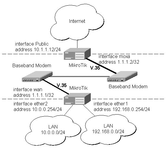
Synchronous Line ApplicationsTwo possible synchronous line configurations are discussed in the following examples: MikroTik Router to MikroTik RouterLet us consider the following network setup with two MikroTik Routers connected to a leased line with baseband modems:
The driver for MOXA C101 card should be loaded and the interface should be enabled according to the instructions given above. The IP addresses assigned to the synchronous interface should be as follows:
[MikroTik] ip address> add address 1.1.1.1/32 interface wan \
network 1.1.1.2 broadcast 255.255.255.255
[MikroTik] ip address> print
  # ADDRESS         NETMASK         NETWORK         BROADCAST       INTERFACE
  0 10.0.0.254      255.255.255.0   10.0.0.254      10.0.0.255      ether2
  1 192.168.0.254   255.255.255.0   192.168.0.254   192.168.0.255   ether1
  2 1.1.1.1         255.255.255.255 1.1.1.2         255.255.255.255 wan
[MikroTik] ip address> /ping 1.1.1.2
1.1.1.2 pong: ttl=255 time=27 ms
1.1.1.2 pong: ttl=255 time=27 ms
1.1.1.2 pong: ttl=255 time=27 ms
3 packets transmitted, 3 packets received, 0% packet loss
round-trip min/avg/max = 27/27.0/27 ms
[MikroTik] ip address>
Note, that for the point-to-point link the network mask is set to 32 bits, the argument 'network' is set to the IP address of the other end, and the broadcast address is set to 255.255.255.255. The default route should be set to the gateway router 1.1.1.2: [MikroTik] ip route> add gateway 1.1.1.2 interface wan [MikroTik] ip route> pr # DST-ADDRESS NETMASK GATEWAY PREF-ADDRESS INTE... 0 10.0.0.0 255.255.255.0 0.0.0.0 10.0.0.213 ether2 D K 1 192.168.0.0 255.255.255.0 0.0.0.0 192.168.0.254 ether1 D K 2 1.1.1.2 255.255.255.255 0.0.0.0 1.1.1.1 wan D K 3 0.0.0.0 0.0.0.0 1.1.1.2 0.0.0.0 wan [MikroTik] ip route> The configuration of the Mikrotik router at the other end is similar:
[MikroTik] ip address> add address 1.1.1.2/32 interface moxa \
network 1.1.1.1 broadcast 255.255.255.255
[MikroTik] ip address> print
  # ADDRESS         NETMASK         NETWORK         BROADCAST       INTERFACE
  0 10.1.1.12       255.255.255.0   10.1.1.12       10.1.1.255      Public
  1 1.1.1.2         255.255.255.255 1.1.1.1         255.255.255.255 moxa
[MikroTik] ip address> /ping 1.1.1.1
1.1.1.1 pong: ttl=255 time=27 ms
1.1.1.1 pong: ttl=255 time=27 ms
1.1.1.1 pong: ttl=255 time=27 ms
3 packets transmitted, 3 packets received, 0% packet loss
round-trip min/avg/max = 27/27.0/27 ms
[MikroTik] ip address>
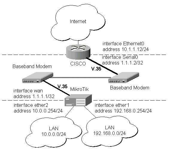
Let us consider the following network setup with MikroTik Router connected to a leased line with baseband modems and a CISCO router at the other end:
The driver for MOXA C101 card should be loaded and the interface should be enabled according to the instructions given above. The IP addresses assigned to the synchronous interface should be as follows: [MikroTik] ip address> add address 1.1.1.1/32 interface wan \ network 1.1.1.2 broadcast 255.255.255.255 [MikroTik] ip address> print # ADDRESS NETMASK NETWORK BROADCAST INTERFACE 0 10.0.0.254 255.255.255.0 10.0.0.254 10.0.0.255 ether2 1 192.168.0.254 255.255.255.0 192.168.0.254 192.168.0.255 ether1 2 1.1.1.1 255.255.255.255 1.1.1.2 255.255.255.255 wan [MikroTik] ip address> /ping 1.1.1.2 1.1.1.2 pong: ttl=255 time=27 ms 1.1.1.2 pong: ttl=255 time=27 ms 1.1.1.2 pong: ttl=255 time=27 ms 3 packets transmitted, 3 packets received, 0% packet loss round-trip min/avg/max = 27/27.0/27 ms [MikroTik] ip address> Note, that for the point-to-point link the network mask is set to 32 bits, the argument 'network' is set to the IP address of the other end, and the broadcast address is set to 255.255.255.255. The default route should be set to the gateway router 1.1.1.2: [MikroTik] ip route> add gateway 1.1.1.2 interface wan [MikroTik] ip route> pr # DST-ADDRESS NETMASK GATEWAY PREF-ADDRESS INTE... 0 10.0.0.0 255.255.255.0 0.0.0.0 10.0.0.213 ether2 D K 1 192.168.0.0 255.255.255.0 0.0.0.0 192.168.0.254 ether1 D K 2 1.1.1.2 255.255.255.255 0.0.0.0 1.1.1.1 wan D K 3 0.0.0.0 0.0.0.0 1.1.1.2 0.0.0.0 wan [MikroTik] ip route> The configuration of the CISCO router at the other end (part of the configuration) is: CISCO#show running-config Building configuration... Current configuration: ... ! interface Ethernet0 description connected to EthernetLAN ip address 10.1.1.12 255.255.255.0 ! interface Serial0 description connected to MikroTik ip address 1.1.1.2 255.255.255.252 serial restart-delay 1 ! ip classless ip route 0.0.0.0 0.0.0.0 10.1.1.254 ! ... end CISCO# Send ping packets to the MikroTik router:
CISCO#ping 1.1.1.1

Type escape sequence to abort.
Sending 5, 100-byte ICMP Echos to 1.1.1.1, timeout is 2 seconds:
!!!!!
Success rate is 100 percent (5/5), round-trip min/avg/max = 28/32/40 ms
CISCO#
|
Overview
PPTP (Point to Point Tunnel Protocol) supports encrypted tunnels over IP. The Mikrotik RouterOS implementation includes a PPTP client, a PPTP dynamic server, and a PPTP static server. The following tunnels are supported:
General usage of PPTP tunnels:
Topics covered in this section:
PPTP Installation on the MikroTik RouterOS v2.3
The pptp-2.3.0.npk(less than 160KB) package and the ppp-2.3.0.npk(less than 370KB) are required. The package can be downloaded from MikroTiks web page www.mikrotik.com . To install the packages, please upload them to the router with ftp and reboot. You may check to see if the PPTP and PPP packages are installed with the command:
[mikrotik]> system package print
  # NAME                                             VERSION    BUILD UNINSTALL
  0 routing                                          2.3.6      5     no
  1 aironet                                          2.3.6      5     no
  2 wavelan                                          2.3.6      5     no
  3 system                                           2.3.6      5     no
  4 snmp                                             2.3.6      5     no
  5 option                                           2.3.6      5     no
  6 ppp                                              2.3.6      5     no
  7 pptp                                             2.3.6      5     no
  8 pppoe                                            2.3.6      5     no
  9 radiolan                                         2.3.6      5     no
 10 ssh                                              2.3.6      5     no
[mikrotik]>
Lines six and seven show that the PPTP and PPP packages are installed.
Hardware resource usage
PPTP uses a minimum amount of memory. The current version of PPTP on RouterOS v2.3 uses a CPU intensive system which will run 5.6Mb/s on a Celeron 600MHz CPU. RouterOS v2.4 has a re-written PPTP engine that will run approximately 60Mb/s on a Celeron 600MHz CPU.
PPTP protocol description
Though the following may sound complex, our implementation of PPTP is easy to setup and manage. PPTP, together with PPP, is a secure tunnel for transporting IP traffic. PPTP encapsulates PPP in virtual lines that run over IP. PPTP incorporates PPP and MPPE (Microsoft point to point encryption) to make encrypted links. The purpose of this protocol is to make well-managed secure connections between 1) routers and routers 2) routers and Windows clients (or other OS with PPTP support). PPTP includes PPP authentication and accounting for each PPTP connection. Full authentication and accounting of each connection may be done through a RADIUS client or locally. There are also additional PPP configurations for management of users and connections. MPPE 40bit RC4 and MPPE 128bit RC4 encryption are supported. PPTP traffic uses TCP port 1723 and IP protocol ID 47, as assigned by the Internet Assigned Numbers Authority (IANA). PPTP can be used with most firewalls and routers by enabling traffic destined for port 1723 to be routed through the firewall or router. PPTP connections cannot be setup though a masqueraded/NAT IP connection. Please see the Microsoft and RFC links at the end of this section for more information.
PPTP client setup
Each PPTP connection is composed of a server and a client. The MikroTik RouterOS may function as a server or client or for various configurations, it may be the server for some connections and client for other connections. For example, the client created below could connect to a Windows 2000 server, another MikroTik Router, or another router which supports a PPTP server. To add a PPTP client to the router:
[Rack1u] interface pptp-client> add name rack2u pap no chap no ms-chapv2 yes encryption required user testDescriptions of settings:
connect-to 10.5.8.171 idle-timeout 0 session-timeout 0
[Rack1u] interface pptp-client> print
(0) name: rack2u mtu: 1460 mru: 1460 pap: no chap: no ms-chapv2: yes
encryption: required user: test connect-to: 10.5.8.171 idle-timeout: 0
session-timeout: 0
nameFor a reference.
Pap, chap, ms-chapv2Encrypted links are only supported when ms-chapv2 is selected. This is a feature of the protocol. It is suggested that pap and chap always be set to no, unless there is a special situation which requires an unencrypted link.
encryption
Will only work in encrypted mode when ms-chapv2 authentication is used. For most links, it should be set to required.
none no encryption
optional 40bit or 128bit if server requests this
required 40bit or 128bit if server agrees, link will be shut down if no agreement
non-stateless (description) key is changed approximately every hour or depending on traffic
stateless same as required plus key is changed for every packet
user
A user name and password must be added to the client routers user database. The user must be added with the attribute of group PPP. When the client is being authenticated by the server, the client will send this user and the password from the client routers user database. The server user database must have the same user and password and PPP group attribute to authenticate the link.
Connect-toThe IP address of the PPTP server.
idle-timeout
The link will be terminated if there is no activity with-in the time set in seconds. When set to 0, there is no timeout.
session-timeout
The maximum time the connection can stay up. When set to 0, there is no timeout.
client-address
IP address of client connecting to the PPTP static server
PPTP dynamic server setup
The router supports one PPTP dynamic server. This server supports unlimited connections from clients. For each current connection, a dynamic interface is created. While the PPTP dynamic server supports multiple clients, it does not support static routes, filters, and other IP level features that need to be attached to static interfaces. The PPTP static server supports routes and other IP level features.
To add a dynamic server:
[Rack2u] interface pptp-dynamic-server server> set enabled yes pap no chap no ms-chapv2 yes encryption required
local-address-from 10.9.0.1 local-address-to 10.9.0.1 remote-address-from 10.9.0.1 remote-address-to 10.9.0.100
[Rack2u] interface pptp-dynamic-server server> print
enabled: yesDescriptions of settings:
pap: no
chap: no
ms-chapv2: yes
encryption: required
mtu: 1460
mru: 1460
idle-timeout: 0
session-timeout: 0
local-address-from: 10.9.0.1
local-address-to: 10.9.0.1
remote-address-from: 10.9.0.2
remote-address-to: 10.9.0.100
enabled
Yes or No
Pap, chap, ms-chapv2Encrypted links are only supported when ms-chapv2 is selected. This is a feature of the protocol. It is suggest that pap and chap always be set to no, unless there is a special situation which requires an unencrypted link.
encryption
Will only work in encrypted mode when ms-chapv2 authentication is used. For most links, it should be set to required.
none no encryption
optional 40bit or 128bit if client agrees to this
required 40bit or 128bit if client agrees, link will be shut down if no agreement
non-stateless (description) key is changed approximately every hour or depending on traffic
stateless same as required plus key is changed for every packet
mtu
The default mtu is set to 1460 because of the PPTP overhead. It may be changed for special situations.
mru
The default mru is set to 1460 because of the PPTP overhead. It may be changed for special situations.
idle-timeout
The link will be terminated if there is no activity with-in the time set in seconds. When set to 0, there is no timeout.
session-timeout
The maximum time the connection can stay up. When set to 0, there is no timeout.
local-address-from and local-address-to
The IP address of the PPTP local server. Both the -from and to can be the same. The same local server address will be used on all connections that are created.
remote-address-from and remote-address-to
This should be set to an IP range. This may limit the number of current connections if there are no free IPs available when a new connection is initiated.
PPTP static server setup
The PPTP static server is made for permanent connections between two routers. One side of the PPTP tunnel must be set up as a static server and the other side as a client. On both the static server side and the client side, it will be possible to add static routes, filters, and any other IP level features for example an EoIP tunnel may be put on top of the PPTP encrypted tunnel to make an encrypted LAN-to-LAN bridge.
To add a PPTP static server interface:
[Rack2u] interface pptp-static-server> add name rack1u client-address 10.5.8.169 pap no chap no ms-chapv2 yesDescriptions of settings:
encryption required local-address 10.7.0.1 remote-address 10.7.0.2
[Rack2u] interface pptp-static-server> print
(0) name: rack1u client-address: 10.5.8.169 pap: no chap: no ms-chapv2: yes encryption: required
mtu: 1460 mru: 1460 idle-timeout: 0 session-timeout: 0 local-address: 10.7.0.1 remote-address: 10.7.0.2
Pap, chap, ms-chapv2
Encrypted links are only supported when ms-chapv2 is selected. This is a feature of the protocol. It is suggest that pap and chap always be set to no, unless there is a special situation which requires an unencrypted link.
encryption
Will only work in encrypted mode when ms-chapv2 authentication is used. For most links, it should be set to required.
none no encryption
optional 40bit or 128bit if client agrees to this
required 40bit or 128bit if client agrees, link will be shut down if no agreement
non-stateless (description) key is changed approximately every hour or depending on traffic
stateless same as required plus key is changed for every packet
mtu
The default mtu is set to 1460 because of the PPTP overhead. It may be changed for special situations.
mru
The default mru is set to 1460 because of the PPTP overhead. It may be changed for special situations.
idle-timeout
A standard PPP setting. The link will be terminated if there is no activity with-in the time set in seconds. When set to 0, there is no timeout.
session-timeout
The maximum time the connection can stay up. When set to 0, there is no timeout.
local-address
The IP address of the PPTP local server. The same local server address can be used on multiple static sever interfaces.
remote-address
This should be set to an IP address of the remote client. PPTP connections for this static server will only be accepted from this address.
PPTP monitoring
To monitor a PPTP client:
[Rack1u] interface pptp-client> mon 0Descriptions of display:
uptime: 2s
encoding: MPPE 128 bit, stateless
status: Connected
uptime


Connection time displayed in days, hours, minutes, and seconds.
encoding
Encryption being used in this connection.
statusThe status of this client may be:
Dialing attempting to make a connection
Connected self-explanatory
Terminated interface is not enabled or the other side will not establish a connection
PPTP router-to-router secure tunnel example
The following is an example of connecting two Intranets using an encrypted PPTP tunnel over the Internet.
There are three routers in this example:
HomeOffice
Interface LocalHomeOffice 10.150.2.254/24
Interface ToInternet 192.168.80.1/24
Internet
Interface ToHomeOffice 192.168.80.254/24
Interface ToRemoteOffice 192.168.81.254/24
RemoteOffice
Interface ToInternet 192.168.81.1/24To add a secure Tunnel between the HomeOffice and RemoteOffice local Intranet, add an identical user and password with the group ppp to both the HomeOffice and RemoteOffice router.
Interface LocalRemoteOffice 10.150.1.254/24
[RemoteOffice] user> add name remote password remote group pppAdd a PPTP static server interface to the HomeOffice router -
[HomeOffice] user> add name remote password remote group ppp
[HomeOffice] interface pptp-static-server> print
0   name: FromRemoteOffice client-address: 192.168.81.1 pap: no chap: no
    ms-chapv2: yes encryption: required mtu: 1460 mru: 1460 idle-timeout: 0
    session-timeout: 0 local-address: 10.0.103.1 remote-address: 10.0.103.2
Add a PPTP client to the RemoteOffice router
[RemoteOffice] interface pptp-client> pr
0   name: Tunnel_To_HomeOffice mtu: 1460 mru: 1460 pap: no chap: no
    ms-chapv2: yes encryption: required user: remote connect-to: 192.168.80.1
    idle-timeout: 0 session-timeout: 0
To route the local Intranets over the PPTP tunnel add these routes
To the HomeOffice router
  # DST-ADDRESS     NETMASK         GATEWAY         PREF-ADDRESS    INTE...
  4 10.150.2.0      255.255.255.0   10.0.103.1      0.0.0.0         Tunn...
To the RemoteOffice router
  # DST-ADDRESS     NETMASK         GATEWAY         PREF-ADDRESS    INTE...
  7 10.150.1.0      255.255.255.0   10.0.103.2      0.0.0.0         From...
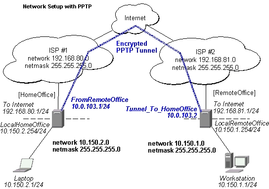
Test the PPTP tunnel connection
[RemoteOffice]> /ping 10.0.103.1
10.0.103.1 pong: ttl=255 time=3 ms
10.0.103.1 pong: ttl=255 time=3 ms
10.0.103.1 pong: ttl=255 time=3 ms
ping interrupted
3 packets transmitted, 3 packets received, 0% packet loss
round-trip min/avg/max = 3/3.0/3 ms
Test the connection through the PPTP tunnel to the Intranet interface
[RemoteOffice]> /ping 10.150.2.254To bridge a LAN over this secure tunnel, please the EoIP section of the manual. To set the maximum speed for traffic over this tunnel, please the Queues section.
10.150.2.254 pong: ttl=255 time=3 ms
10.150.2.254 pong: ttl=255 time=3 ms
10.150.2.254 pong: ttl=255 time=3 ms
ping interrupted
3 packets transmitted, 3 packets received, 0% packet loss
round-trip min/avg/max = 3/3.0/3 ms
PPTP Windows setup
Microsoft provides PPTP client support for Windows NT, 2000, ME, 98se, and 98. Windows 98se, 2000, and ME include support in the Windows setup or automatically install PPTP. For 95, NT, and 98, installation requires a download from Microsoft. Many ISPs have made help pages to assist clients with Windows PPTP installation. A zipped download of an instructional web page is available in PPTP_client_files.zip this can be found in the utilities section of the download section. This zipped file also includes files needed from Microsoft for upgrading Windows 95 and 98 to support PPTP.
Links:
http://www.real-time.com/Customer_Support/PPTP_Config/pptp_config.html
http://www.microsoft.com/windows95/downloads/contents/WUAdminTools/S_WUNetworkingTools/W95WinsockUpgrade/Default.asp
Sample instructions for PPTP (VPN) installation and client setup Windows 98se:
If the VPN (PPTP) support is installed, select Dial-up networking and create a new connection. The option to create a VPN should be selected. If there is no VPN options, then follow the installation instructions below. When asked for the Host name or IP address of the VPN server, type the IP address of the router. Double-click on the new icon and type the correct user name and password (must also be in the user database on the router or RADIUS server used for authentication). The setup of the connections takes nine seconds after selection the connect button. It is suggested that the connection properties be edited so that NetBEUI, IPX/SPX compatible, and Log on to network, are unselected. The setup time for the connection will then be two seconds after the connect button is selected.Links for PPTP documentation:
http://msdn.microsoft.com/library/backgrnd/html/understanding_pptp.htm
http://support.microsoft.com/support/kb/articles/q162/8/47.asp
http://www.ietf.org/rfc/rfc2637.txt?number=2637
http://www.ietf.org/rfc/rfc3078.txt?number=3078
http://www.ietf.org/rfc/rfc3079.txt?number=3079
This document applies to MikroTik RouterOS V2.4
Overview
The PPPoE (Point to Point Protocol over Ethernet) protocol provides extensive user management, network management, and accounting benefits to ISPs and network administrators. Currently, PPPoE is used mainly by ISPs to control client connections for xDSL and cable modems. PPPoE is an extension of the standard dial-up and synchronous protocol PPP. The transport is over Ethernet as opposed to modem transport. A PPPoE connection is composed of a client and an access concentrator (server). The client may be a Windows computer that has the PPPoE client protocol installed. The MikroTik RouterOS supports both the client and access concentrator implementations of PPPoE. The PPPoE client and server work over any Ethernet level interface on the router wireless 802.11 (Aironet, Cisco, WaveLAN), 10/100/1000 Mb/s Ethernet, RadioLAN, and EoIP (Ethernet over IP tunnel). No encryption, MPPE 40bit RSA, and MPPE 128bit RSA encryption are supported. Our RouterOS has a RADIUS client that can be used for authentication of all PPP type connections including PPPoE. For more information on PPP authentication, see the PPP Authentication and Accounting section of the manual.
Supported connections:
· MikroTik RouterOS PPPoE client to any PPPoE server (access concentrator)
· MikroTik RouterOS server (access concentrator) to multiple PPPoE clients (clients are available for all OSs and some routers)
Topics covered in this manual:
· Installation
· Hardware resource usage
· PPPoE client setup
· PPPoE server setup (access concentrator)
· PPPoE bandwidth settings
· PPPoE in a multipoint wireless 802.11b network
The pppoe-2.4.0.npk(less than 160KB) package and the ppp-2.4.0.npk(less than 370KB) are required. The package can be downloaded from MikroTiks web page www.mikrotik.com . To install the packages, please upload them to the router with ftp and reboot. You may check to see if the packages are installed with the command:
[mikrotik]> system package print
  # NAME                                             VERSION    BUILD UNINSTALL
  0 routing                                          2.4.0      1     no
  1 aironet                                          2.4.0      1     no
  2 wavelan                                          2.4.0      1     no
  3 system                                           2.4.0      1     no
  4 snmp                                             2.4.0      1     no
  5 option                                           2.4.0      1     no
  6 ppp                                              2.4.0      1     no
  7 pptp                                             2.4.0      1     no
  8 pppoe                                            2.4.0      1     no
  9 radiolan                                         2.4.0      1     no
 10 ssh                                              2.4.0      1     no

[mikrotik]>
Lines six and eight show that the PPP and PPPoE packages are installed.
The PPPoE client supports high-speed connections. It is fully compatible with the MikroTik PPPoE server (access concentrator). Test with different ISPs and access concentrators are currently underway.
Some connection instructions may use the form where the phone number is MikroTik_AC\mt1 to indicate that MikroTik_AC is the access concentrator name and mt1 is the service name.
[RemoteOffice] interface pppoe-client> print0 name=pppoe-out1 interface=gig service-name=testSN user=john pap=no chap=yes ms-chapv2=no mtu=1492 mru=1492 idle-timeout=0s session-timeout=0s add-default-route=yes dial-on-demand=no use-peer-dns=no encryption=none compression=no local-address=0.0.0.0 remote-address=0.0.0.0 ac-name="" mss-update=1452Descriptions of settings:
nameThis settable name will appear in interface and IP address list when the PPPoE session is active.
interfaceThe PPPoe client can be attached to any Ethernet like interface for example: wireless, 10/100/1000 Ethernet, and EoIP tunnels.
mtu and mruRepresents the MTU and MRU when the 8 byte PPPoE overhead is subtracted from the standard 1500 byte Ethernet packet
Pap, chap, ms-chapv2It is suggested that chap be set to yes to have encrypted authentication. If there is a special situation that requires an encrypted link, only ms-chapv2 should be set to yes. Encrypted links are only supported when ms-chapv2 is selected. This is a requirement of the protocol.
encryptionWill only work in encrypted mode when ms-chapv2 authentication is used. For most links, it should be set to none.
none no encryption
optional 40bit or 128bit if server requests this
required 40bit or 128bit if server agrees, link will be shut down if no agreement
non-stateless (description) key is changed approximately every hour or depending on traffic
stateless same as required plus key is changed for every packet
user
A user name and password must be added to the client routers user database. The user must be added with the attribute of group PPP. When the server is authenticating the client, the client will send this user and the password from the client routers user database. The server user database must have the same user and password and PPP group attribute to authenticate the link unless the RADIUS client is enabled.
idle-timeoutThe link will be terminated if there is no activity with-in the time set in seconds. When set to 0, there is no timeout.
session-timeoutThe maximum time the connection can stay up. When set to 0, there is no timeout.
dial-on-demandConnects to AC only when outbound traffic is generated. The client will not stay permanently connected.
use-peer-dnsSets the router default DNS to the PPP peer DNS.
compressionMay be selected if encryption is not used. The default setting of no compression is suggested.
local-addressIf the ppp server allows, a local-address may be set. The default setting of 0.0.0.0 is suggested. In this case, the address set by the server will be used.
session-timeoutThe maximum time the connection can stay up set in seconds. When set to 0, there is no timeout.
remote-addressIf the ppp server allows, a remote-address may be set. The default setting of 0.0.0.0 is suggested.
serviceThe service name set on the access concentrator. Many ISPs give user-name and address in the form of user-name@service-name
ac-nameThis may be left blank and the client will connect to any access concentrator that offers the service name selected.
Add-default-routeSelect yes to have a default route added automatically.
mss-updateThis setting changes the mss (maximum segment size) setting of each packet to the selected size. The default of 1452 is suggested. This fixes a common problem for PPPoE when mis-configured servers or networks do not let the IP protocol work properly. The common symptom is a partial download of a web page.
PPPoE server setup (access concentrator)
The PPPoE server (access concentrator) supports multiple servers for each interface with differing service names. Currently, a maximum of 5000 PPPoE connections are supported. Currently the throughput of the PPPoE server has been tested to 160Mb/s on a Celeron 600 CPU. Using higher speed CPUs should increase the throughput proportionately.
The setting below is the optimal setting to work with Windows clients such as RASPPPoE client for Win98/2000/ME. The password authentication and encryption are set to pap no chap yes ms-chapv2 no encryption none specifically to ensure a quick login by the windows client. In the example below, the login is encrypted with PAP. Currently it is possible to make encrypted links to Windows clients, but usually they quit passing IP after five minutes but remain connected and do show that data is passed this is a bug which is being worked on. There are no problems with encryption between MikroTik PPPoE client and server.
The access concentrator has a hard limit of 5000 current connections. The user setting for the connections limit is done by setting the remote-to and remote-from IP addresses range. For example, For a limit of 1020 users: remote-from=10.0.0.1 remote-to=10.0.4.255 . Even if you are using a RADIUS server for client addresses, the remote-from and remote-to arguments must include an IP range which will limit/enable the number of current connections.
The access concentrator name and PPPoE service name are used by clients to identify the access concentrator to register with. The access concentrator name name is the same as the identity of the router. The identity many be set with the command: /system identity set xxxxx .
  0   service-name=testSN interface=gig local-from=5.5.5.1 local-to=5.5.5.1

      remote-from=6.6.6.1 remote-to=6.6.6.250 mtu=1492 mru=1492 pap=no chap=yes

      ms-chapv2=no idle-timeout=0s session-timeout=0s compression=no

      encryption=none
Descriptions of settings:
Pap, chap, ms-chapv2It is suggest that chap always be set to yes. PAP is best disabled because it sends the user-name and password in clear text. ms-chapv2 should be disable as it is not needed unless there is a special situation that requires an encrypted link. Encrypted links are only supported when ms-chapv2 is selected. This is a feature of the protocol.
encryption
Will only work in encrypted mode when ms-chapv2 authentication is used. For most setups, it should be set to none.
none no encryption
optional 40bit or 128bit if client agrees to this
required 40bit or 128bit if client agrees, link will be shut down if no agreement
non-stateless (description) key is changed approximately every hour or depending on traffic
stateless same as required (non-stateless) plus key is changed for every packet
interface
The PPPoe server can be attached to any Ethernet like interface for example: wireless, 10/100/1000 Ethernet, and EoIP tunnels.
compressionStandard PPP level compression.
serviceThe PPPoE service name.
mtuThe default mtu is set to 1492 because of the PPPoE overhead. It may be changed for special situations.
mruThe default mru is set to 1492 because of the PPPoE overhead. It may be changed for special situations.
idle-timeoutA standard PPP setting. The link will be terminated if there is no activity with-in the time set in seconds. When set to 0, there is no timeout.
session-timeoutThe maximum time the connection can stay up in the format of Xh or Xm or Xs. When set to 0, there is no timeout.
local-address-from and local-address-toThe IP address pool of the PPPoE local server for each new PPPoE connection. One local address can be used on multiple static sever interfaces. Usually, it is best that this is not a real IP address. Only the client could have a use for a real IP address. Example: local-address-from 10.0.0.1 local-address-to 10.0.0.1 .
remote-address-from and remote-address-toThe IP address pool for the PPPoE remote client for each new PPPoE connection. One address must be available for each current connection the number in the range selected will be the maximum number of current connections. If radius authentication is used to give addresses, it is still required to have a range of addresses set in this server setup.
Links for PPPoE documentation:
http://www.ietf.org/rfc/rfc2516.txt
http://www.nts.com/products/enternet_overvw.html
http://www.carricksolutions.com/
http://www.cisco.com/warp/public/cc/pd/as/6400/prodlit/6400_ds.htm
Copyright 2001, MikroTik
Overview
The IPIP tunneling implementation on the MikroTik RouterOS is RFC 2003 compliant. IPIP tunnel is a simple protocol that encapsulates IP packets in IP to make a tunnel between two routers. The IPIP interface appears as an interface. Many routers, including Cisco and Linux based, support this protocol. This protocol makes multiple network schemes possible.
Network setups with IPIP interfaces:
Topics covered in this section:
IPIP installation on the MikroTik RouterOS v2.3
The IPIP tunnel feature is included in the system package.
Hardware resource usage
This protocol uses a minimum of resources.
IPIP interface and protocol description
An IPIP interface should be configured on two routers that have the possibility for an IP level connection and are RFC 2003 compliant. The IPIP tunnel may run over any connection that transports IP. Each IPIP tunnel interface can connect with one remote router which has a corresponding interface configured. An unlimited number of IPIP tunnels may be added to the router. For more details on IPIP tunnels, see RFC 2003.
IPIP setup
To add an IPIP interface:
[Rack1u] interface ipip> add name test_IPIP mtu 1480 local-address 10.5.8.169 remote-address 10.5.8.171Descriptions of settings:
[Rack1u] interface ipip> print
(0) name: test_IPIP mtu: 1480 local-address: 10.5.8.169
remote-address: 10.5.8.171
nameInterface name for reference
mtuShould be set to 1480 bytes to avoid fragmentation of packets. May be set to 1500bytes if mtu path discovery is not working properly on links.
local-addressLocal address on router which send IPIP traffic to the remote side.
remote-address
The IP address of the other side of the IPIP tunnel may be any RFC 2003 compliant router.
There is no authentication or state for this interface. The bandwidth usage of the interface may be monitored with the monitor feature from the interface menu.
IPIP Cisco example
Our IPIP implementation has been tested with Cisco 1005. Sample of the Cisco 1005 configuration:
interface Tunnel0
 ip address 10.3.0.1 255.255.255.0
tunnel source 10.5.8.179
tunnel destination 10.5.8.169
tunnel mode ipip
Additional Resources
Links for IPIP documentation:
http://www.ietf.org/rfc/rfc1853.txt?number=1853
http://www.ietf.org/rfc/rfc2003.txt?number=2003
http://www.ietf.org/rfc/rfc1241.txt?number=1241
Overview
Ethernet over IP (EoIP) Tunneling is a RouterOS protocol that creates an Ethernet tunnel between two routers on top of an IP connection. The EoIP interface appears as an Ethernet interface. When the bridging function of the router is enabled, all Ethernet level traffic (all Ethernet protocols) will be bridged just as if there where a physical Ethernet interface and cable between the two routers (with bridging enabled). This protocol makes multiple network schemes possible.
Network setups with EoIP interfaces:
Topics covered in this section:
EoIP installation on the MikroTik RouterOS v2.3
The Ethernet over IP tunnel feature is included in the system package.
Hardware resource usage
To achieve 100Mb/s Ethernet level wire speed (85Mb/s), it is suggested that Celeron 600MHz and higher CPUs be used on each router in this situation, the CPU usage was ~60%. Optimization of this implementation will soon decrease the usage of resource usage.
EoIP interface and protocol description
An EoIP interface should be configured on two routers that have the possibility for an IP level connection. The EoIP tunnel may run over an IPIP tunnel, a PPTP 128bit encrypted tunnel, a PPPoE connection, or any connection that transports IP. Each EoIP tunnel interface can connect with one remote router which has a corresponding interface configured with the same Tunnel ID. Up to sixteen (numbered 0-15) EoIP tunnels may be created on a router (please contact us if there is an important reason to increase the number of EoIP tunnels per router). The EoIP interface appears as an Ethernet interface under the interface list. This interface supports all features of and Ethernet interface. IP addresses and other tunnels may be run over the interface. The EoIP protocol encapsulates Ethernet frames in UDP packets and sends them to the remote side of the EoIP tunnel. The tunnel transmits and listens to the UDP port 4444 + tunnel ID.
EoIP setup
To add an EoIP interface:
[Rack1u] interface eoip> add name to_2u tunnel-id 1 remote-address 10.5.8.171
0 name: to_2u mtu: 1500
mac-address: FE:FD:00:00:00:00 arp: enabled
tunnel-id: 1 remote-address: 10.111.0.1
Descriptions of settings:
name
Interface name for reference
mtu
Should be set to 1500bytes.
mac-address
A default virtual MAC address is generated. It may be changed if there is a conflict.
arp
Enabled by default.
tunnel-id
Should be a number from 0-16 which has not been used for another EoIP tunnel.
remote-address
The IP address of the other side of the EoIP tunnel must be a MikroTik router.
To make an Ethernet bridge between two routers with EoIP tunnels, bridging should be enabled on both routers. There is no authentication or state for this interface. The bandwidth usage of the interface may be monitored with the monitor feature from the interface menu.
Managing ISDN Server from Console
It is done from "interface isdn-server" submenu.
| Command Syntax | Description |
|---|---|
|
|
Print ISDN Server information |
|
set <number> [name <interface name>] [enable] [disable] [mtu <MTU>] [mru <MRU>] |
Configure ISDN Server |
|
remove <number> |
Remove ISDN Server |
|
find |
Find |
|
export |
Export ISDN Server settings |
| monitor <interface> | Monitor ISDN server in real time |
Where <interface> is an interface name or number obtained from "print" command.
Managing ISDN Client from JAVA
It is done from Interfaces list. To add isdn client you have to choose add
and then ISDN client. If you want to change isdn client settings you have to double click on added isdn client interface in Interace list.Managing ISDN Client from Console
It is done from "interface isdn-client" submenu.
| Command Syntax | Description |
|---|---|
|
|
Print ISDN Client information |
|
set <number> [name <interface name>] [enable] [disable] [mtu <MTU>] [mru <MRU>] |
Configure ISDN Client |
|
remove <number> |
Remove ISDN Client |
|
find |
Find |
|
export |
Export ISDN Client settings |
| monitor <interface> | Monitor ISDN Client in real time |
Where <interface> is an interface name or number obtained from "print" command.
Managing LMC- WAN from Console
It is done from "lmc-wan" submenu.
| Command Syntax | Description |
|---|---|
|
|
Print LMC-WAN information |
|
set <number> [name <interface name>] [enable] [disable] [mtu <MTU>] |
Configure LMC-WAN |
|
find |
Find |
|
export |
Export LMC-WAN settings |
| monitor <interface> | Monitor LMC-WAN in real time |
Where <interface> is an interface name or number obtained from "print" command.
For more information about the CISCO/Aironet PCI/ISA adapter hardware please see the relevant
Users Guides and Technical Reference Manuals in .pdf format:
Documentation about CISCO/Aironet Wireless Bridges and Access Points can be found in archives:
Contents of the Manual
The following topics are covered in this manual:
[mikrotik]> system package print
  # NAME                                                VERSION    BUILD UNINSTALL
  0 system                                              2.3.7      8     no
  1 ppp                                                 2.3.7      6     no
  2 pppoe                                               2.3.7      10    no
  3 pptp                                                2.3.7      6     no
  4 routing                                             2.3.7      7     no
  5 ssh                                                 2.3.6      7     no
  6 aironet                                             2.3.7      6     no
[mikrotik]>
[mikrotik]> system resource irq print
IRQ OWNER
1   keyboard                                                                  U
2   APIC                                                                      U
3   Local                                                                     U
4   serial port                                                               U
5
6
7
8
9
10
11  Public                                                                    U
12
13  FPU                                                                       U
14  IDE 1                                                                     U
[mikrotik]> system resource io print
IO        OWNER
0020-003f APIC
0040-005f timer
0060-006f keyboard
0080-008f DMA
00a0-00bf APIC
00c0-00df DMA
00f0-00ff FPU
01f0-01f7 IDE 1
0300-031f Local
03c0-03df VGA
03f6-03f6 IDE 1
03f8-03ff serial port
6100-61ff Public
f000-f007 IDE 1
f008-f00f IDE 2
Installing the Wireless Adapter
The basic installation steps of the wireless adapter should be as follows:
Loading the Driver for the Wireless Adapter
PCI and PC (PCMCIA) cards do not require a 'manual' driver loading, since they
are recognized automatically by the system and the driver is loaded at the system startup.
The ISA card requires the driver to be loaded by issuing the following command:
[mikrotik]> driver load pc-isa io 0x180
[mikrotik]> driver print
  # DRIVER                                       IRQ IO     MEMORY     ISD...
  0 RealTek RTL8129/8139                                                      D
  1 ISA NE2000                                       0x300
  2 Aironet ISAxx00                                  0x180
[mikrotik] driver>
There can be several reasons for a failure to load the driver:
[mikrotik] interface> print
  # NAME                                                    TYPE        MTU
  0 Public                                                  ether       1500
  1 Local                                                   ether       1500
 (2)pc0                                                     pc          1500
[mikrotik] interface> set 2 name aironet
[mikrotik] interface> enable aironet
[mikrotik] interface> print
  # NAME                                                    TYPE        MTU
  0 Public                                                  ether       1500
  1 Local                                                   ether       1500
  2 aironet                                                 pc          1500
More configuration and statistics parameters can be found under the '/interface pc' menu:
[mikrotik] interface> pc
[mikrotik] interface pc> print
0   name: aironet mtu: 1500 mac-address: 00:40:96:29:02:88
    mode: infrastructure rts-threshold: 2312 fragmentation-threshold: 2312
    tx-power: 100 rx-diversity: right tx-diversity: right long-retry-limit: 16
    short-retry-limit: 16 channel: 2437MHz data-rate: auto
    ap1: 00:00:00:00:00:00 ap2: 00:00:00:00:00:00 ap3: 00:00:00:00:00:00
    ap4: 00:00:00:00:00:00 ssid1: tsunami ssid2: "" ssid3: "" modulation: cck
    client-name: "" beacon-period: 100 join-net: 10s arp: enabled
    firmware-version: PC4800A(3.65)

[mikrotik] interface pc>
Argument description:
number - Interface number in the list
name - Interface name
mtu - Maximum Transmit Unit
mode - Operation mode of the card (infrastructure / ad-hoc)
rts-threshold - RTS threshold
fragmentation-threshold - Fragmentation threshold
tx-power - Transmit power in mW
rx-diversity - Receive diversity (both / default / left / right)
tx-diversity - Transmit diversity (both / default / left / right)
long-retry-limit - Long retry limit
short-retry-limit - Short retry limit
channel - Channel frequency (2412MHz / 2422MHz / ... / 2484MHz)
data-rate - Data rate (11Mbit/s / 1Mbit/s / 2Mbit/s / 5.5Mbit/s / auto)
ap1 - Access Point 1
ap2 - Access Point 2
ap3 - Access Point 3
ap4 - Access Point 4
ssid1 - Service Set Identifier 1
ssid2 - Service Set Identifier 2
ssid3 - Service Set Identifier 3
modulation - Modulation mode (cck / default / mbok)
client-name - Client name
join-net - Beaconing period
arp - Address Resolution Protocol (disabled / enabled / proxy-arp)
You can monitor the status of the wireless interface:
[mikrotik] interface pc> monitor 0
              quality: 0
             strength: 0
         current-rate: 11Mbit/s
    current-frequency: 2437MHz
         synchronized: no
           associated: no
                 ssid: tsunami
         access-point: FF:FF:FF:FF:FF:FF
    access-point-name:

[mikrotik] interface pc>
If the wireless interface card is not registered to an AP, the green status led is blinking fast.
To set the wireless interface for working with an IEEE 802.11b access point (register to the AP), you should set the following parameters:
[mikrotik] interface pc> set 0 ssid1 mt
[mikrotik] interface pc> monitor 0
              quality: 63
             strength: 131
         current-rate: 11Mbit/s
    current-frequency: 2412MHz
         synchronized: yes
           associated: yes
                 ssid: mt
         access-point: 00:40:96:00:06:72
    access-point-name: Gulf
[mikrotik] interface pc>
If the wireless interface card is registered to an AP, the green status led is blinking slow.
Two possible wireless network configurations are discussed in the following examples:
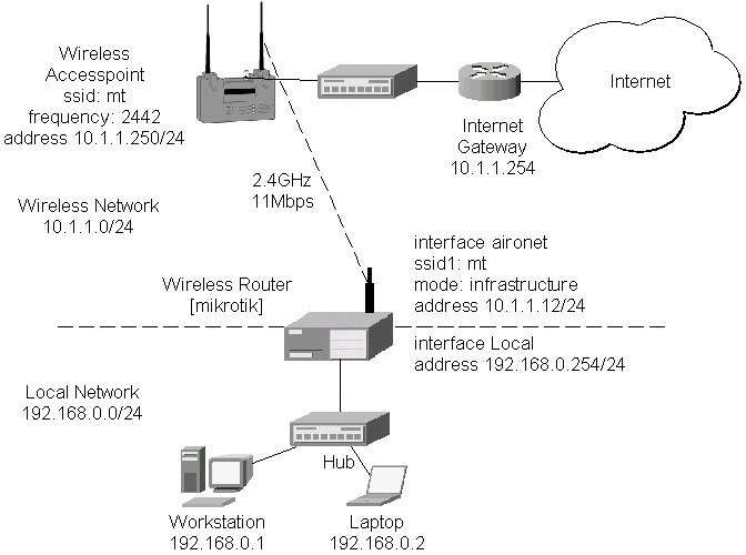
The access point is connected to the wired network's HUB and has IP address from the network 10.1.1.0/24. The minimum configuration required for the AP is:
Reminder! Please note, that the AP is not a router! It has just one network address, and is just like any host on the network. It resembles a wireless-to-Ethernet HUB or bridge. The AP does not route the IP traffic!
The minimum configuration for the MikroTik router's CISCO/Aironet wireless interface is:
[mikrotik] interface pc> set 0 ssid1 mt mode infrastructure
[mikrotik] interface pc> monitor 0
              quality: 62
             strength: 129
         current-rate: 11Mbit/s
    current-frequency: 2442MHz
         synchronized: yes
           associated: yes
                 ssid: mt
         access-point: 00:40:96:00:06:72
    access-point-name: Gulf
[mikrotik] interface pc>
The channel frequency argument does not have any meaning, since the frequency of the AP is used. The IP addresses assigned to the wireless interface should be from the network 10.1.1.0/24, e.g.:
[mikrotik] ip address> add address 10.1.1.12/24 interface aironet
[mikrotik] ip address> print
  # ADDRESS         NETMASK         NETWORK         BROADCAST       INTERFACE
  0 192.168.0.254   255.255.255.0   192.168.0.254   192.168.0.255   Local
  1 10.1.1.12       255.255.255.0   10.1.1.12       10.1.1.255      aironet
[mikrotik] ip address>
The default route should be set to the gateway router 10.1.1.254 (not the AP 10.1.1.250 !):
[mikrotik] ip route> add gw 10.1.1.254 interface aironet
[mikrotik] ip route> print
  # DST-ADDRESS     NETMASK         GATEWAY         PREF-ADDRESS    INTE...
  0 192.168.0.0     255.255.255.0   0.0.0.0         192.168.0.254   Local   D K
  1 10.1.1.0        255.255.255.0   0.0.0.0         10.1.1.12       aironet D K
  2 0.0.0.0         0.0.0.0         10.1.1.254      0.0.0.0         aironet
[mikrotik] ip route>
Arlan IC2200 interfaces include Aironets Arlan IC2200 (655) 2.4GHz 2Mbps ISA Client Cards. This hardware line has been discontinued.
Managing Arlan IC2200 Interfaces from Java
Arlan IC2200 specific parameters can be controlled from the Radio tab in interface details window. Current status (registration status and registered router and backbone) can be monitored in real time on Status tab in interface details window.
Managing Arlan IC2200 Interfaces from Console
Arlan IC2200 interface management is done in the submenu interface arlan.
| Command syntax | Description |
|---|---|
|
print [<interface>] |
Show interface(s) information |
|
set <interface> [enable] [disable]
|
Change interface properties |
|
monitor <interface> |
Monitor interface status in real time |
|
find |
|
|
export |
Where <interface> is interface name or number obtained from print command.
Interface status includes registration status and registered router and backbone.
Arlan IC2200 Parameter Description
| Name in Console | Name in Java | Description |
|---|---|---|
|
frequency |
Frequency |
Channel frequency in MHz. |
|
bitrate |
Bitrate |
Data Transmission speed in Mbits |
|
card-name |
Card Name |
Name of the client to be shown in the registration table of the Access Point or Bridge. Maximum 15 characters. |
|
sid |
SID |
Value of System Identifier. Should be the same for all nodes on the radio network. Maximum 31 character. |
|
mac-address |
MAC Address |
Medium Access Control Address |
|
tma-mode |
TMA mode |
Enable/Disable registration mode when client has to register to an AP2000 Access Point or BR2000-E Bridge. |
|
arp |
ARP |
Address Resolution Protocol settings |
For more information about the RadioLAN adapter hardware please see the relevant Users Guides and Technical Reference Manuals.
Contents of the Manual
The following topics are covered in this manual:
[MikroTik]> system package print
  # NAME                                             VERSION    BUILD UNINSTALL
  0 routing                                          2.3.15     21    no
  1 snmp                                             2.3.15     15    no
  2 ppp                                              2.3.15     20    no
  3 pptp                                             2.3.15     21    no
  4 pppoe                                            2.3.15     22    no
  5 ssh                                              2.3.15     26    no
  6 system                                           2.3.15     32    no
  7 radiolan                                         2.3.15     16    no
[MikroTik]>
[MikroTik]> system resource irq print
IRQ OWNER
1   keyboard                                                                  U
2   APIC                                                                      U
3
4   serial port                                                               U
5
6
7
8
9   ether1                                                                    U
10
11
12
13  FPU                                                                       U
14  IDE 1                                                                     U
[MikroTik]> system resource io print
IO        OWNER
0020-003f APIC
0040-005f timer
0060-006f keyboard
0080-008f DMA
00a0-00bf APIC
00c0-00df DMA
00f0-00ff FPU
01f0-01f7 IDE 1
02f8-02ff serial port
03c0-03df VGA
03f6-03f6 IDE 1
03f8-03ff serial port
ef00-efff ether1
fc00-fc07 IDE 1
fc08-fc0f IDE 2
fc10-fc7f [CS5530]
[MikroTik]>
Installing the Wireless Adapter
The basic installation steps of the wireless adapter should be as follows:
Loading the Driver for the Wireless Adapter
The ISA card requires the driver to be loaded by issuing the following command:
[MikroTik]> driver load radiolan io 0x300
[MikroTik]> driver print
  # DRIVER                                       IRQ IO     MEMORY     ISD...
  0 RealTek RTL8129/8139                                                      D
  1 ISA RadioLAN                                     0x300
[MikroTik]>
There can be several reasons for a failure to load the driver:
[MikroTik] interface> print
  # NAME                                                    TYPE        MTU
  0 ether1                                                  ether       1500
( 1)radiolan1                                               radiolan    1500
[MikroTik] interface> enable radiolan1
[MikroTik] interface> print
  # NAME                                                    TYPE        MTU
  0 ether1                                                  ether       1500
  1 radiolan1                                               radiolan    1500
[MikroTik] interface>
More configuration and statistics parameters can be found under the '/interface radiolan' menu:
[MikroTik] interface> radiolan
[MikroTik] interface radiolan> print
0   name: radiolan1 mtu: 1500 mac-address: 00:A0:D4:20:42:EE distance: 0-150m
    tx-diversity: disabled rx-diversity: disabled default-dst: firstclient
    max-retries: 15 sid: bbbb card-name: 00A0D42042EE
    cfg-destination: 00:00:00:00:00:00 arp: enabled

[MikroTik] interface radiolan>
Argument description:
number - Interface number in the list
name - Interface name
mtu - Maximum Transmit Unit
mac-address - MAC address
distance - distance setting for the link (0-10.2km)
rx-diversity - Receive diversity (disabled / enabled)
tx-diversity - Transmit diversity (disabled / enabled)
default-dst - deafault destination (alone / ap / cfg / firstap / firstclient). It sets the destination where to send the packet if it is not for a clinet in the radio network.
max-retries - maximum retries before dropping the packet
sid - Service Set Identifier
card-name - Card name
cfg-destination - MAC address of a host in the radio network where to send the packet, if it is for none of the radio clients.
arp - Address Resolution Protocol (disabled / enabled / proxy-arp)
You can monitor the status of the wireless interface:
[MikroTik] interface radiolan> monitor radiolan1
    default: 00:00:00:00:00:00
      valid: no
[MikroTik] interface radiolan>
Here, the wireless interface card has not found any neighbour.
To set the wireless interface for working with another wireless card in a point-to-point link, you should set the following parameters:
[MikroTik] interface radiolan> set 0 sid ba72 distance 4.7km-6.6km
[MikroTik] interface radiolan> print
0   name: radiolan1 mtu: 1500 mac-address: 00:A0:D4:20:42:EE
    distance: 4.7km-6.6km tx-diversity: disabled rx-diversity: disabled
    default-dst: firstclient max-retries: 15 sid: ba72 card-name: 00A0D42042EE
    cfg-destination: 00:00:00:00:00:00 arp: enabled

[MikroTik] interface radiolan> monitor 0
    default: 00:A0:D4:20:42:47
      valid: yes

[MikroTik] interface radiolan>
You can monitor the list of neighbours having the same sid and being within the radio range:
[MikroTik] interface radiolan> neighbours print radiolan1
NAME             MAC-ADDRESS       FLAGS ACCESS-POINT
00A0D4204247     00:A0:D4:20:42:47    D
[MikroTik] interface radiolan>
You can test the link by pinging the neighbour by its MAC address:
[MikroTik] interface radiolan> ping radiolan1 \
mac-address 00:A0:D4:20:42:47 size 1500 count 50
Sent: 2/50 (4%), Ok: 2/2 (100%) max/avg/min retries: 0/0.0/0
Sent: 12/50 (24%), Ok: 12/12 (100%) max/avg/min retries: 0/0.0/0
Sent: 22/50 (44%), Ok: 22/22 (100%) max/avg/min retries: 0/0.0/0
Sent: 32/50 (64%), Ok: 32/32 (100%) max/avg/min retries: 0/0.0/0
Sent: 42/50 (84%), Ok: 42/42 (100%) max/avg/min retries: 0/0.0/0
Sent: 50/50 (100%), Ok: 50/50 (100%) max/avg/min retries: 0/0.0/0
[MikroTik] interface radiolan>
Two possible wireless network configurations are discussed in the following examples:
Point-to-Point Setup with Routing Let us consider the following network setup with two MikroTik Routers having RadioLAN interfaces:The IP addresses assigned to the wireless interface of Router#1 should be from the network 10.1.0.0/30, e.g.:
[MikroTik] ip address> add address 10.1.0.1/30 interface radiolan1
[MikroTik] ip address> print
  # ADDRESS         NETMASK         NETWORK         BROADCAST       INTERFACE
  0 10.1.0.1        255.255.255.252 10.1.0.1        10.1.0.3        radiolan1
  1 10.1.1.12       255.255.255.0   10.1.1.12       10.1.1.255      ether1
[MikroTik] ip address>
The default route should be set to the gateway router 10.1.1.254. A static route should be added for the network 192.168.0.0/24:
[MikroTik] ip route> add gateway 10.1.1.254 interface ether1
[MikroTik] ip route> add dst-address 192.168.0.0/24 gateway 10.1.0.2 \
interface radiolan1
[MikroTik] ip route> print
  # DST-ADDRESS     NETMASK         GATEWAY         PREF-ADDRESS    INTE...
  0 10.1.1.0        255.255.255.0   0.0.0.0         10.1.1.12       ether1  D K
  1 10.1.0.0        255.255.255.252 0.0.0.0         10.1.0.1        radi... D K
  2 192.168.0.0     255.255.255.0   10.1.0.2        0.0.0.0         radi...
  3 0.0.0.0         0.0.0.0         10.1.1.254      0.0.0.0         ether1
[MikroTik] ip route>
For more information about the WaveLAN / ORiNOCO adapter hardware please see the relevant
Users Guides and Technical Reference Manuals in .pdf format from the manufacturer:
Information about configuring the ORiNOCO wireless access point can be found there:
Contents of the Manual
The following topics are covered in this manual:
[MikroTik] system package> print
  # NAME                                             VERSION    BUILD UNINSTALL
  0 routing                                          2.3.15     21    no
  1 snmp                                             2.3.15     15    no
  2 ppp                                              2.3.15     20    no
  3 pptp                                             2.3.15     21    no
  4 pppoe                                            2.3.15     22    no
  5 ssh                                              2.3.15     26    no
  6 system                                           2.3.15     32    no
  7 option                                           2.3.15     20    no
  8 wavelan                                          2.3.15     21    no
[MikroTik] system package>
[[MikroTik] system resource> irq print
IRQ OWNER
1   keyboard                                                                  U
2   APIC                                                                      U
3
4
5
6
7
8
9
10  ether1                                                                    U
11
12
13  FPU                                                                       U
14  IDE 1                                                                     U
[MikroTik] system resource> io print
IO        OWNER
0020-003f APIC
0040-005f timer
0060-006f keyboard
0080-008f DMA
00a0-00bf APIC
00c0-00df DMA
00f0-00ff FPU
01f0-01f7 IDE 1
03c0-03df VGA
03e0-03e1 PCMCIA service
03f6-03f6 IDE 1
6100-611f ether1
[MikroTik] system resource>
Installing the Wireless Adapter
The basic installation steps of the wireless adapter should be as follows:
Loading the Driver for the Wireless Adapter
The WaveLAN / Orinoco PC (PCMCIA) cards do not require a 'manual' driver loading, since they
are recognized automatically by the system and the driver is loaded at the system startup.
If the driver has loaded successfully, there should be two beeps of equal tone,
which should be heard through the PC's speaker while the system startup.
If the second beep has a lower tone than the first one, then the driver could not be loaded,
or, there is no wavelan package installed.
Note! The PC card can be inserted in the PCMCIA-ISA or PCI adapter when the system is running. The wavelan driver is not listed under the list of loaded drivers.
There can be several reasons for a failure to load the driver:
[MikroTik] interface> print
  # NAME                                                    TYPE        MTU
  0 ether1                                                  ether       1500
( 1)wavelan1                                                wavelan     1500
[MikroTik] interface> enable 1
[MikroTik] interface> print
  # NAME                                                    TYPE        MTU
  0 ether1                                                  ether       1500
  1 wavelan1                                                wavelan     1500
[MikroTik] interface>
More configuration and statistics parameters can be found under the '/interface wavelan' menu:
[MikroTik] interface> wavelan
[MikroTik] interface wavelan> print
0   name: wavelan1 mtu: 1500 mac-address: 00:02:2D:07:17:23 channel: 2412MHz
    date-rate: 11Mbit/s mode: ad-hoc ssid: "" client-name: "" key1: ""
    key2: "" key3: "" key4: "" tx-key: key1 encryption: no arp: arp

[MikroTik] interface wavelan>
Argument description:
number - Interface number in the list
name - Interface name
mtu - Maximum Transmit Unit (256...2296 bytes). The default value is 1500 bytes.
mac-address - MAC address of the card. Cannot be changed.
channel - Channel frequency (2412MHz / 2422MHz / ... / 2484MHz)
data-rate - Data rate (11Mbit/s / 1Mbit/s / 2Mbit/s / 5.5Mbit/s / auto)
mode - Operation mode of the card (infrastructure / ad-hoc)
ssid - Service Set Identifier
client-name - Client name
key1 - Encryption key #1
key2 - Encryption key #2
key3 - Encryption key #3
key4 - Encryption key #4
tx-key - Transmit key (key1 / key2 / key3 / key4)
encryption - Encryption (no / yes)
arp - Address Resolution Protocol (disabled / enabled / proxy-arp)
You can monitor the status of the wireless interface:
[MikroTik] interface wavelan> monitor wavelan1
             bssid: 00:00:00:00:00:00
           channel: 2422MHz
         data-rate: 2Mbit/s
              ssid:
    signal-quality: 0
      signal-level: 154
             noise: 154
[MikroTik] interface wavelan>
If the wireless interface card is not registered to an AP, the green status led is blinking fast.
To set the wireless interface for working with an IEEE 802.11b access point (register to the AP), you should set the following parameters:
[MikroTik] interface wavelan> set 0 ssid MT_w_AP
[MikroTik] interface wavelan> monitor wavelan1
             bssid: 00:60:B3:66:C7:40
           channel: 2452MHz
         data-rate: 11Mbit/s
              ssid: MT_w_AP
    signal-quality: 56
      signal-level: 213
             noise: 157
[MikroTik] interface wavelan>
Two possible wireless network configurations are discussed in the following examples:
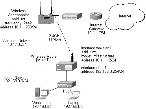
The access point is connected to the wired network's HUB and has IP address from the network 10.1.1.0/24. The minimum configuration required for the AP is:
Reminder! Please note, that the AP is not a router! It has just one network address, and is just like any host on the network. It resembles a wireless-to-Ethernet HUB or bridge. The AP does not route the IP traffic!
The minimum configuration for the MikroTik router's wavelan wireless interface is:
[MikroTik] interface wavelan> set wavelan1 ssid mt
[MikroTik] interface wavelan> monitor wavelan1
             bssid: 00:60:B3:66:C7:40
           channel: 2442MHz
         data-rate: 11Mbit/s
              ssid: mt
    signal-quality: 56
      signal-level: 214
             noise: 158
[MikroTik] interface wavelan>
The channel frequency argument does not have any meaning, since the
frequency of the AP is used.
IP Network Configuration
The IP addresses assigned to the wireless interface should be from the network 10.1.1.0/24, e.g.:
[MikroTik] ip address> add address 10.1.1.12/24 interface wavelan1
[MikroTik] ip address> add address 192.168.0.254/24 interface ether1
[MikroTik] ip address> print
  # ADDRESS         NETMASK         NETWORK         BROADCAST       INTERFACE
  0 10.1.1.12       255.255.255.0   10.1.1.12       10.1.1.255      wavelan1
  1 192.168.0.254   255.255.255.0   192.168.0.254   192.168.0.255   ether1
[MikroTik] ip address>
The default route should be set to the gateway router 10.1.1.254 (not the AP 10.1.1.250 !):
[MikroTik] ip route> print
  # DST-ADDRESS     NETMASK         GATEWAY         PREF-ADDRESS    INTE...
  0 10.1.1.0        255.255.255.0   0.0.0.0         10.1.1.12       wave... D K
  1 192.168.0.0     255.255.255.0   0.0.0.0         192.168.0.254   ether1  D K
  2 0.0.0.0         0.0.0.0         10.1.1.254      0.0.0.0         wave...
[MikroTik] ip route>
Document revision 09-Aug-2001
This document applies to the V2.4 of the MikroTik RouterOS
For more information about adapter hardware please see the relevant
Users Guides and Technical Reference Manuals of the hardware manufacturers.
The MikroTik RouterOS supports the PrismII chipset based wireless adapter cards for working both as wireless clients (station mode) and wireless access points (access point mode).
[MikroTik] > sys package print
  # NAME                   VERSION               BUILD-TIME           UNINSTALL
  0 routing                2.4rc6                aug/06/2001 15:56:22 no
  1 snmp                   2.4rc6                aug/06/2001 15:56:24 no
  2 ppp                    2.4rc6                aug/06/2001 15:56:37 no
  3 pptp                   2.4rc6                aug/06/2001 15:56:47 no
  4 pppoe                  2.4rc6                aug/06/2001 15:56:53 no
  5 ssh                    2.4rc6                aug/06/2001 15:58:11 no
  6 system                 2.4rc6                aug/06/2001 15:56:04 no
  7 prism                  2.4rc6                aug/06/2001 15:58:54 no
[MikroTik] >
The 2.4GHz Wireless Feature License enables only the station mode of the Prism II card. To enable the access point mode, additionally the Wireless AP Feature License is required.
The MikroTik RouterOS supports as many PrismII chipset based cards as many free resources are on your system, i.e., IRQs and adapter slots. One license is valid for all cards on your system.
[MikroTik] > system resource irq print
 IRQ USED OWNER
 1   yes  keyboard
 2   yes  APIC
 3   no
 4   yes  serial port
 5   no
 6   no
 7   no
 8   no
 9   yes  ether1
 10  no
 11  no
 12  no
 13  yes  FPU
 14  yes  IDE 1
[MikroTik] > system resource io print
 PORT-RANGE            OWNER
 32-63                 APIC
 64-95                 timer
 96-111                keyboard
 128-143               DMA
 160-191               APIC
 192-223               DMA
 240-255               FPU
 496-503               IDE 1
 760-767               serial port
 960-991               VGA
 992-993               PCMCIA service
 1014-1014             IDE 1
 1016-1023             serial port
 61184-61439           ether1
 64512-64519           IDE 1
 64520-64527           IDE 2
 64528-64639           [CS5530]
[MikroTik] >
There can be several reasons for a failure to load the driver, for example:
[MikroTik] > interface print
Flags: X - disabled, D - dynamic
  #   NAME                 MTU   TYPE
  0   ether1               1500  ether
  2 X prism1               1500  prism
[MikroTik] > interface enable 1
[MikroTik] > interface set 1 name=wireless
[MikroTik] > interface print
Flags: X - disabled, D - dynamic
  #   NAME                 MTU   TYPE
  0   ether1               1500  ether
  1   wireless             1500  prism
[MikroTik] >
More configuration and statistics parameters can be found under the '/interface prism' menu:
[MikroTik] interface prism> print
Flags: X - disabled
  0   name=wireless mtu=1500 mac-address=00:03:C0:00:06:72 arp=enabled
      mode=station frequency=2412MHz ssid=abc client-name=""
      max-associations=250 hide-ssid=no supported-rates=1-11 basic-rates=1-2
      fragmentation-threshold=2346 rts-threshold=2432
      default-access-action=allow

[MikroTik] interface prism>
Argument description:
number - Interface number in the list
name - Interface name (same as for other interfaces)
mtu - Maximum transfer unit (same as for other interfaces)
mac-address - MAC address of card. In AP mode this will also be BSSID of BSS.
arp - ARP mode (same as for ethernet interfaces)
mode - (station|access-point). If station - card works as station, if access-point, card works as access point. After mode is changed from access-point to station, for station mode to activate, have to reboot (changing back to AP mode will work fine). Change from station to AP can be done without rebooting.
frequency - Frequency that AP will use to create BSS
ssid - Service Set Identifier. In station mode - ssid to connect to, in AP mode - ssid to use when creating BSS (this can not be left blank, because AP needs ssid to work, but in station mode cards hang up without ssid.
client-name - Client name
max-associations - meaningless for station. For AP means how many stations can be associated at the same time (min: 1, max: 500)
hide-ssid - meaningless for station. For AP tells that SSID should not be transmitted in beacon frames (so none can read ssid when sniffing radio), and that AP should not answer probe requests that do not have our ssid in them. Basically this means that if this setting is set to "yes", every client that wants to connect to this AP has to have correct ssid configured.
supported-rates - For both - station and AP - rates at which this node will work.
basic-rates - Meaningless for station. For AP - rates that every client that plans to connect to this AP should be able to work at.
fragmentation-threshold - for both STA and AP - bigger packets than this value will be fragmented before transmission (min: 256, max: 2346)
rts-threshold - for both STA and AP - bigger packets than this value will be transmitted using RTS/CTS medium reservation method. This medium reservation ensures that no other radios transmit at this time (min: 0, max: 2432)
default-access-action - (allow|deny) - meaningless for STA, for AP - what to do with client that wants to associate, but it is not in the access-list.
You can monitor the status of the wireless interface:
[MikroTik] interface prism> monitor 0
       signal-quality: 0
         signal-level: 27
          noise-level: 27
         current-rate: 2
               status: disconnected

[MikroTik] interface prism>
Station Mode Configuration
To set the wireless interface for working with an IEEE 802.11b access point (register to the AP),
you should set the following parameters:
[MikroTik] interface prism> set 0 ssid=mt
[MikroTik] interface prism> monitor 0
                bssid: 00:40:96:37:71:1E
    current-frequency: 2442MHz
       signal-quality: 92
         signal-level: 183
          noise-level: 0
         current-rate: 8
               status: connected

[MikroTik] interface prism>
If the wireless interface card is registered to an AP.
Access Point Mode Configuration
To set the wireless interface for working as an IEEE 802.11b access point (register clients),
you should set the following parameters:
All other parameters can be left as default. To configure the wireless interface for working as an access point with ssid "mt" and use the frequency 2442MHz, it is enough to enter the command:
[MikroTik] interface prism> set 0 mode=access-point ssid=mt frequency=2442MHz
[MikroTik] interface prism> monitor
                bssid: 00:03:C0:00:06:72
    current-frequency: 2442MHz
               status: ap-mode

[MikroTik] interface prism>
To see the list of all clients currently registered to all configured APs,
[MikroTik] interface prism> registration-table print
  # INT MAC-ADDRESS       SIGNAL     SILENCE    RATE       UPTIME
  0 wir 00:40:96:37:71:1E 183        0          11         00:03:32
  1 wir 00:40:96:29:02:88                                  00:01:15
[MikroTik] interface prism>
Argument description for the registration-table entry:
mac-address - mac address of the registered client
interface - interface that client is registered to
signal - signal level
silence - silence level
rate - current rate
uptime - how long client is connected
The monitor command gives additional per-client statistics:
[MikroTik] interface prism> registration-table monitor 0
        packets: 13,2
          bytes: 0,616
            bps: 0.0bps/0.0bps,0.0bps/4.10kbps
            pps: 0/1,0/1
         signal: 171/186/195
        silence: 0/0/0
           rate: 11/11/11
    last-update: 00:00:02
         uptime: 00:09:01

[MikroTik] interface prism>
Ta add an access list entry for MAC address 00:40:96:37:71:1E, use command:
[MikroTik] interface prism access-list> add allow=yes interface=wireless \
mac-address=00:40:96:37:71:1E
[MikroTik] interface prism access-list> print
Flags: X - disabled, I - invalid
  #   MAC-ADDRESS       ALLOW INTERFACE
  0   00:40:96:37:71:1E yes   wireless
[MikroTik] interface prism access-list>
Argument description:
allow - (yes|no) - accept this client when it tries to connect or not
interface - AP interface
mac-address - MAC address of the client
If you have default access action for the interface set to 'allow', you can disallow this node to register at the AP's interface 'wireless' by changing the 'allow' argument value to 'no':
[MikroTik] interface prism access-list> .. print
Flags: X - disabled
  0   name=wireless mtu=1500 mac-address=00:03:C0:00:06:72 arp=enabled
      mode=access-point frequency=2442MHz ssid=mt client-name=MT_Prism
      max-associations=250 hide-ssid=no supported-rates=1-11 basic-rates=1-2
      fragmentation-threshold=2346 rts-threshold=2432
      default-access-action=allow

[MikroTik] interface prism access-list> set 0 allow=no
[MikroTik] interface prism access-list> print
Flags: X - disabled, I - invalid
  #   MAC-ADDRESS       ALLOW INTERFACE
  0   00:40:96:37:71:1E no    wireless
[MikroTik] interface prism access-list>
Thus, all nodes except this one will be able to register to the interface 'wireless'.
If you have default access action for the interface set to 'deny', you can allow this node to register at the AP's interface 'wireless' by changing the 'allow' argument value to back 'yes':
[MikroTik] interface prism access-list> .. print
Flags: X - disabled
  0   name=wireless mtu=1500 mac-address=00:03:C0:00:06:72 arp=enabled
      mode=access-point frequency=2442MHz ssid=mt client-name=MT_Prism
      max-associations=250 hide-ssid=no supported-rates=1-11 basic-rates=1-2
      fragmentation-threshold=2346 rts-threshold=2432
      default-access-action=deny

[MikroTik] interface prism access-list> set 0 allow=yes
[MikroTik] interface prism access-list> print
Flags: X - disabled, I - invalid
  #   MAC-ADDRESS       ALLOW INTERFACE
  0   00:40:96:37:71:1E yes   wireless
[MikroTik] interface prism access-list>
Two possible wireless network configurations are discussed in the following examples:
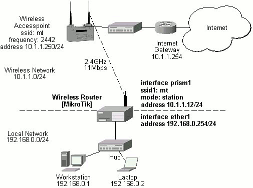
The access point is connected to the wired network's HUB and has IP address from the network 10.1.1.0/24. The minimum configuration required for the AP is:
Reminder! Please note, that the AP is not a router! It has just one network address, and is just like any host on the network. It resembles a wireless-to-Ethernet HUB or bridge. The AP does not route the IP traffic!
The minimum configuration for the MikroTik router's prism wireless interface is:
[MikroTik] interface prism> set 0 ssid=mt
[MikroTik] interface prism> monitor 0
                bssid: 00:40:96:37:71:1E
    current-frequency: 2442MHz
       signal-quality: 92
         signal-level: 195
          noise-level: 0
         current-rate: 8
               status: connected

[MikroTik] interface prism>
The IP addresses assigned to the wireless interface should be from the network 10.1.1.0/24, e.g.:
[MikroTik] ip address> add address=10.1.1.12/24 interface=prism1
[MikroTik] ip address> print
Flags: X - disabled, I - invalid, D - dynamic
  #   ADDRESS            NETWORK         BROADCAST       INTERFACE
  0   10.1.1.12/24       10.1.1.0        10.1.1.255      prism1
  1   192.168.0.254/24   192.168.0.254   192.168.0.254   ether1
[MikroTik] ip address>
The default route should be set to the gateway router 10.1.1.254 (not the AP 10.1.1.250 !):
[MikroTik] ip route> add gateway=10.1.1.254
[MikroTik] ip route> print
Flags: X - disabled, I - invalid, D - dynamic, R - rejected
  #    TYPE           DST-ADDRESS        GATEWAY        DISTANCE INTERFACE
  0    static         0.0.0.0/0          10.1.1.254     1        prism1
  1 D  connect        10.1.1.0/24        0.0.0.0        0        prism1
  2 D  connect        192.168.0.254/24   0.0.0.0        0        ether1
[MikroTik] ip route>
Note! You cannot use the bridging function between the prism and ethernet interfaces, if the prism interface is in the station mode. The bridge does not work in this case!
To make the MikroTik router work as an access point,
the configuration of the prism wireless interface should be as follows:
The list of registered clients looks like follows:
There are two possible ways of implementing the wireless access point feature:
The client router requires the System Service Identificator set to "mt".
The IP addresses assigned to the interfaces should be from networks
10.1.1.0/24 and 192.168.0.0./24:
MAC level bridging of Ethernet packets is supported. The router has one internal
bridging table. Interfaces can be included or excluded. Ethernet, Ethernet over
IP (EoIP), and RadioLAN interfaces are supported .Features include:
Topics covered in this section: The Bridge feature is included in the system package.
No installation is needed for this feature. When
Bridge is enabled, it uses a small amount of memory. No increase of memory is suggested. Each
protocol that should be forwarded should be set to forward. Protocols selectable are: appletalk, arp,
ip, ipv6, ipx,
and other. The other
protocol includes are protocols not listed before. priority Set [mikrotik]> bridge set
ip forward yes forward yes Each
interface that should be included in the bridging table should be set to forward.
Set
[mikrotik]> bridge interface set ether1 Example
output of the print command: The
bridge can be monitored in real time. The
bridging table shows the MAC address of hosts, interface which can forward packets
to the host, and the age of the information shown in seconds. Wireless Access Point
Let us consider the following point-to-point wireless network setup with two MikroTik Wireless Routers:
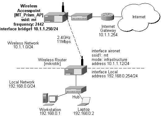
The following command should be issued to change the settings for the prism interface:
[MT_Prism_AP] interface prism> set 0 mode=access-point frequency=2442MHz
[MT_Prism_AP] interface prism> print
Flags: X - disabled
  0   name=prism1 mtu=1500 mac-address=00:03:C0:00:06:72 arp=enabled
      mode=access-point frequency=2442MHz ssid=mt client-name=
      max-associations=250 hide-ssid=no supported-rates=1-11 basic-rates=1-2
      fragmentation-threshold=2346 rts-threshold=2432
      default-access-action=allow

[MT_Prism_AP] interface prism> monitor 0
                bssid: 00:03:C0:00:06:72
    current-frequency: 2442MHz
               status: ap-mode

[MT_Prism_AP] interface prism>
[MT_Prism_AP] interface prism> registration-table print
  # INT MAC-ADDRESS       SIGNAL     SILENCE    RATE       UPTIME
  0 pri 00:40:96:29:02:88 210        0          11         00:12:50
  1 pri 00:40:96:37:71:1E 192        0          11         00:00:35
[MT_Prism_AP] interface prism>
To enable bridging between the ethernet and prism interfaces, do the following:
[MT_Prism_AP] bridge> set ip=forward arp=forward other=forward
[MT_Prism_AP] bridge> print
           ip: forward
          ipx: discard
    appletalk: discard
         ipv6: discard
          arp: forward
        other: forward
     priority: 1
[MT_Prism_AP] bridge>
[MT_Prism_AP] bridge interface> print
  # INTERFACE                                                           FORWARD
  0 ether1                                                              no
  1 prism1                                                              no
[MT_Prism_AP] bridge interface> set ether1 forward=yes
[MT_Prism_AP] bridge interface> set prism1 forward=yes
[MT_Prism_AP] bridge interface> print
  # INTERFACE                                                           FORWARD
  0 ether1                                                              yes
  1 prism1                                                              yes
[MT_Prism_AP] bridge interface>
[MT_Prism_AP] interface> print
Flags: X - disabled, D - dynamic
  #   NAME                 MTU   TYPE
  0   ether1               1500  ether
  1 X bridge1              1500  bridge
  2   prism1               1500  prism
[MT_Prism_AP] interface> enable 1
[MT_Prism_AP] interface> print
Flags: X - disabled, D - dynamic
  #   NAME                 MTU   TYPE
  0   ether1               1500  ether
  1   bridge1              1500  bridge
  2   prism1               1500  prism
[MT_Prism_AP] interface>
[MT_Prism_AP] ip address> add address=10.1.1.250/24 interface=bridge1
[MT_Prism_AP] ip address> print
Flags: X - disabled, I - invalid, D - dynamic
  #   ADDRESS            NETWORK         BROADCAST       INTERFACE
  0   10.1.1.250/24      10.1.1.0        10.1.1.255      bridge1
[MT_Prism_AP] ip address> .. route add gateway=10.1.1.254
[MT_Prism_AP] ip address> .. route print
Flags: X - disabled, I - invalid, D - dynamic, R - rejected
  #    TYPE           DST-ADDRESS        GATEWAY        DISTANCE INTERFACE
  0    static         0.0.0.0/0          10.1.1.254     1        bridge1
  1 D  connect        10.1.1.0/24        0.0.0.0        0        bridge1
[MT_Prism_AP] ip address>
[MikroTik] ip address> print
Flags: X - disabled, I - invalid, D - dynamic
  #   ADDRESS            NETWORK         BROADCAST       INTERFACE
  0   10.1.1.12/24       10.1.1.0        10.1.1.255      aironet
  1   192.168.0.254/24   192.168.0.0     192.168.0.255   Local
[MikroTik] ip address>
The default route should be set to gateway 10.1.1.254 for the router [MikroTik].
5. Bridge
Overview
Bridge installation on the MikroTik RouterOS v2.3
Hardware resource usage
Bridge
setup
[mikrotik] bridge interface> print
# INTERFACE FORWARD
Bridge
Monitoring
[mikrotik] bridge host> print
MAC-ADDRESS ON-INTERFACE AGE
00:C0:DF:07:68:30 ether1 253
Command
Reference
[mikrotik] bridge> ?
Bridging feature is used to pass MAC layer packets between network interfaces.
..
print Show bridge settings
set Change bridge settings
export Export bridge configuration
interface Bridge interfaces
host
[mikrotik] bridge> print
ip: discard
arp: discard
ipx: discard
appletalk: discard
ipv6: discard
other: discard
priority: 1
[mikrotik] bridge interface> ?
..
print Show bridge interfaces
set Change bridge interface settings
find Find bridge interfaces
export Export bridge interfaces settings
[mikrotik] bridge host> ?
..
print
| to the contents |
The Internet Protocol Management section includes configuration of all IP level settings such as IP addresses, DHCP, static routes, and so on.
Addresses serve as identification when communicating with other network devices. It is possible to add multiple IP addresses to each of the interfaces or to leave interfaces without addresses assigned to them.
Select the IP/Addresses menu. The Addresses List list shows all IP addresses with basic settings. From the Address List window addresses can be edited, added (
), removed (), enabled (), disabled () and commented (). You can also disable and enable addresses and comment them. Some addresses (when using PPP) can appear and disappear dynamically. Dynamic addresses are marked with blue icon, others with yellow. Inactive addresses (their interfaces are disabled) are shown in gray and italic. Managing Addresses from ConsoleSelect address in the ip menu.
| Command syntax | Description |
|---|---|
|
add interface <name> |
Add new address |
|
set <number> interface
<name> |
Change address properties |
|
find [from] [dynamic] [inactive] |
|
|
remove <number> |
Remove address |
|
|
Show addresses |
|
comment <number> <comments> |
Add comments to address |
|
enable |
Enable IP address |
|
disable |
Disable IP address |
|
export [file <filename>] |
Export addresses |
| Name in Console | Name in Java | Description |
|---|---|---|
|
interface |
Interface |
Name of interface the address will be used with |
|
address |
Local Address |
Local IP address for the interface |
|
netmask |
Network Mask |
Network Mask to be used with the prefix |
|
network |
Network Prefix |
(optional) Network Prefix to be used with the address. It shows what network can be reached through the interface with the given IP address. If not specified, will be the same as the local address |
|
broadcast |
Broadcast Address |
(optional) Broadcast Address to be used with the address. If not specified, will be calculated from Local Address and Network Mask. |
Routes are needed for communicating with networks that are not directly attainable via the routers local interfaces. Routes to locally connected interfaces and networks are created automatically based on the IP address assigned to local interfaces. Static routes, including the default route, are set in the IP/Routes menu. Other automatic routes are created by routing daemons, such as RIP and OSPF, which can be found in the Routing menu from the base level. Dynamic routes are shown in IP/Routes, too.
Select the Routes menu under the IP menu. The Routes List shows current routes settings which can be edited, added, and deleted. Disabled routes (interface they are using is disabled) are shown in gray and italic. Dynamic routes are marked with blue icon, others with green.
Select the submenu ip route.
| Command Syntax | Description |
|---|---|
|
add interface <name> |
Add new route |
|
set <number> interface
<name> |
Change route properties |
|
find [from] [dynamic] |
|
|
remove <number> |
Remove route |
|
comment <number> |
Add comments to route (only permanent ones) |
|
enable <number> |
Enable address (only permanent ones) |
|
disable <number> |
Disable address (only permanent ones) |
|
|
Show routes |
|
export [file <filename>] |
Export routes |
| Name in Console | Name in Java | Description |
|---|---|---|
|
dst-address |
Dst. Address |
Destination IP address of a host or network |
|
netmask |
Netmask |
Network Mask of the destination |
|
gateway |
Gateway |
Next gateway to the destination |
|
interface |
Interface |
Interface to be used |
|
pref-address |
Pref. Source |
(optional) Source Address of packets leaving the router via this route |
ARP (Address Resolution Protocol) displays IP addresses and respective MAC addresses of interfaces which are physically connected to local interface. The ARP table entries appear automatically as it sends broadcast messages to all interfaces physically connected to the local interfaces. It is possible to manually assign static ARP entries.
Select the ARP menu under the IP menu. The ARP List displays IP addresses, MAC addresses, and interface names and allows to edit, add, and remove ARP entries. Inactive entries are shown in gray color and italic font.
Select the located in address menu that is in the ip menu.
| Command Syntax | Description |
|---|---|
|
add interface <name> |
Add static ARP entry |
|
set <number> |
Change ARP entry |
|
remove <number> |
Remove ARP entry |
|
comment <number> |
Comment ARP entry |
|
enable <number> |
Enable ARP entry |
|
disable <number> |
Disable ARP entry |
|
|
Show ARP entries |
|
export |
Export ARP entries |
| Name in Console | Name in Java | Description |
|---|---|---|
|
address |
IP Address |
IP address |
|
mac-address |
Hardware Address |
MAC address |
|
interface |
Interface |
Interface name |
DHCP
Document revision 11-July-2001 Overview
DHCP
(Dynamic Host Configuration Protocol) supports easy distribution of IP
addresses for a network. The MikroTik
RouterOS implementation includes both server and client modes and is compliant
with RFC2131. General usage of DHCP:
Topics covered in this manual:
DHCP Installation on the MikroTik RouterOS v2.3.14 and higher The DHCP server and client are included in the system package. Hardware resource usage The DHCP server does not consume any significant resources. The DHCP client may consume high resource for five to ten seconds when acquiring an address or renewing an address. DHCP protocol description The DHCP protocol give and allocates IP addresses to IP clients. DHCP is basically unsecure and should only be used on secure networks. Port 67 is the DHCP listen port and port 68 is the DHPC transmit port. DHCP client setup The MikroTik RouterOS DHCP client may be attached to one Ethernet like interface. The client will accept an address, netmask, default gateway, and dns server. The IP address will be added to the interface with the netmask. The default gateway will be added to the routing table as a dynamic entry when the DHCP client is disabled, the dynamic default route will be removed. The DNS-server from the DHCP server will be used as the router default DNS if the router DNS is set to 0.0.0.0. To add a DHCP client to the router: [MikroTik_AC] ip dhcp-client> set enabled yes interface ether1 client-id testDescriptions of settings: [MikroTik_AC]The text inside the brackets is the system identity of the router. If the DHCP server requires a host name, then the MikroTik system identity should be set to the same. This system identity will be reported to the DHCP server as the host name. To change the system identity, use the cammand system identity set Mikro2345.
    [MikroTik_AC]> system identity set Mikro2345
    [Mikro2345]>
enabled yesRequired to enable the DHCP client. interfaceCan be set to any Ethernet like interface this includes radio and EoIP tunnels. client-idOptional. If needed, it should correspond to the settings suggested by the network administrator or ISP. DHCP server setup The router supports an individual server for each Ethernet like interface. The MikroTik RouterOS DHCP server supports the basic functions of giving each requesting client an IP address lease, default gateway, and DNS-server information. To add a DHCP server: [MikroTik_AC] ip dhcp-server> set ether1 enabled yes lease-time 72h from-address 10.5.0.1 to-address 10.5.0.100 netmask 255.255.255.0 gateway 10.5.0.254 dns-ser ver 10.5.0.254 domain rm219 [MikroTik_AC] ip dhcp-server> print 0 interface: ether1 enabled: yes from-address: 10.5.0.1 to-address: 10.5.0.100 lease-time: 3 days 0:00:00 netmask: 255.255.255.0 gateway: 10.5.0.254 src-address: 0.0.0.0 dns-server: 10.5.0.254 domain: ether1-area 1 interface: Local219 enabled: no from-address: 0.0.0.0 to-address: 0.0.0.0 lease-time: 0:10:00 netmask: 0.0.0.0 gateway: 0.0.0.0 src-address: 0.0.0.0 dns-server: 0.0.0.0 domain: "" Descriptions of settings: interfaceAll Ethernet like interfaces may run a DHCP server. enabledRequired to enable the DHCP server. from-addressBeginning number of IP address range to give to requesting DHCP clients. This address must be in the range of a static address on the same interface. to-addressEnding number of IP address range to give to requesting DHCP clients. This address must be in the range of a static address on the same interface. lease-timeDictates the time that a client may use an address. Suggested setting is three days 3d. The client will request a new address after this time limit expires. netmaskThe netmask to be given with the IP address coming from the range of addresses that can be given out. gatewayThe default gateway to be used by the DHCP client. source-addressThe address which the DHCP client must use to renew an IP address lease. If there is only one static address on the DHCP server interface and the source-address is left as 0.0.0.0, then the static address will be used. If there are multiple addresses on the interface, an address in the same subnet as the range of given addresses should be used. dns-serverThe DHCP client will use this as the default DNS server. domainThe DHCP client will use this as the DNS domain setting for the network adapter. Additional Resources Links for DHCP documentation: http://www.ietf.org/rfc/rfc2131.txt?number=2131 http://www.isc.org/products/DHCP/ http://www1.fatbrain.com/asp/BookInfo/BookInfo.asp?theisbn=1578701376&from=xjb375 |
The firewall supports filtering and security functions that are used to manage data flows to the router and through it. Along with the Network Address Translation they serve as security tools for preventing unauthorized access to networks.
Filtering rules organized together in chains do packet filtering. Each chain can be considered as a set of rules. There are three default chains, which cannot be deleted. More chains can be added for grouping together filtering rules. When processing a chain, rules are taken from the chain in the order they are listed from the top to the bottom.
Packets entering the router through one of the interfaces are first matched against the filtering rules of the Input chain. If the packet is not dropped or rejected, and it is for the router itself, the packet is delivered locally. If the packet is not dropped or rejected, but it has to be delivered outside the router, then the packet is processed according to the routing table. If the processing is successful, then the packet is matched to the filtering rules of the forward chain. After that, packet is passed to the output interface and processed according to the rules of output chain.
Packets originated from the router are processed according to the output chain only.
Managing Firewall Functions from Java
Select the Firewall menu under the IP menu. Use
and icons to add/remove chains. Double click on the chain to perform operations with rules: add, remove, comment. You can set policy of the chain by clicking on the following icon: .Managing Firewall Functions from Console
Firewall management can be performed from the ip firewall menu.
| Command syntax | Description |
|---|---|
|
|
Print chains information |
|
set <chain number> |
|
|
find |
|
|
add |
|
|
remove |
|
|
comment |
|
|
export |
Export firewall settings |
|
rule |
Firewall chain rules menu |
|
masq |
Masquerading rules menu |
|
static-nat |
ip firewall rule menu commands:
| Command syntax | Description |
|---|---|
|
add <chain> |
Add new rule |
|
set <chain> <rule number>
|
Change rule |
|
remove <chain name or number>
|
Remove rule |
|
move <chain> <source> <destination> |
Move rule in this chain from source number to destination number |
|
find <chain name or number> |
|
|
comment |
|
|
enable |
|
|
disable |
|
|
export |
|
|
print <chain name or number> |
Show rules |
ip firewall masq menu commands:
| Command Syntax | Description |
|---|---|
|
|
| Name in Console | Name in Java | Description |
|---|---|---|
|
action |
Action |
Action to perform |
|
log |
Log |
Turns on or off logs writing option. |
|
src-address |
Source Address |
Source address, mask, and port of the packet. Default port 0 means all ports 1-65535. For ICMP packets, port parameter means ICMP packet type. |
|
dst-address |
Destination Address |
Destination address, mask, and port of the packet Default port 0 means all ports 1-65535. For ICMP packets, port parameter means ICMP packet code. |
|
protocols |
Protocol |
Protocol name of the packet: all, icmp, tcp, udp etc. |
|
interface |
Interface |
Interface name or all for any interface |
|
tcp |
TCP Options |
TCP Options. Can be all include all TCP option packets; syn include only connection establishing packets; nosyn include all TCP option packets except connection establishing packets. Can be specified only if tcp is selected. |
|
target |
Target Chain |
Can be specified if action is jump |
Actions to perform on rules:
| Action name in console | Action name in Java | Description |
|---|---|---|
|
accept |
Accept |
Accept everything |
|
reject |
Reject |
Reject everything and send ICMP reject message |
|
deny |
Deny |
Silently drop the packet (without sending the ICMP reject message) |
|
masq |
Masq |
Use masquerading |
|
return |
Return |
Return to the chain from which this rule has been invoked |
|
jump |
Jump |
Jump to another chain |
| Name in console | Name in Java | Description |
|---|---|---|
|
name |
Name |
Chain name |
|
policy |
Policy |
Chain policy. If no rules are added to this chain, or packet doesnt match any rule, policy is taken into account |
Managing IP Accounting from JAVA
IP Accounting you can manage by choosing IP and then "accounting".
Managing IP Accounting from Console
It is done from "ip accounting" submenu.
| Command Syntax | Description |
|---|---|
|
|
Print accounting settings |
| set
[enabled <yes|no>] [threshold <number>] |
Change accounting settings |
| export | |
| snapshot [take] [print] | Take or print accounting snapshot |
| dropped print | Print dropped packets |
| Command Syntax | Description |
|---|---|
|
|
Print accounting web server configuration |
| set
[enabled <yes|no>] [address <address>] [netmask <mask>] |
Change accounting settings |
| export |
Remark: To use a private address space, NAT is not required. It is required only to map one global IP address and/or port to a local one. Typically, masquerading (a firewall feature) is used to masquerade the local inside network addresses and ports to one global outside IP address and ports.
Please consult the Basic Setup Guide and the Firewall Manual for more information on masquerading.
The NAT rules are applied in the following order:
For more information about NAT, see RFC 1631. For example, you can visit this site: http://www.faqs.org/rfcs/rfc1631.html
Adding a NAT Rule
Usually there are two NAT rules required for mapping one address:port to another one.
One rule is required for mapping incoming packets, one for outgoing packets of a connection.
Only in cases of udp packets (one-directional packet flow), it is enough with
just one NAT rule to modify the packet's address and/or port.
NAT rules can be added using the /ip firewall static-nat add command. The argument description is as follows:
src-address - Source IP address.
src-netmask - Source netmask
src-port - Source port number or range (0-65535). 0 means all ports 1-65535.
dst-address - Destination IP address.
dst-netmask - Destination netmask
dst-port - Destination port number or range (0-65535). 0 means all ports 1-65535.
to-src-address - Translated source IP address.
to-src-netmask - Translated source netmask
to-src-port - Source port number. 0 means no change (leave as it was).
to-dst-address - Translated destination IP address. 0.0.0.0 means no change.
to-dst-netmask - Translated destination netmask
to-dst-port - Translated destination port number. 0 means no change (leave as it was).
interface - Interface, for which the rule should be used
protocol - Protocol
translate - translate or not (yes/no). If 'no', then the packet is passed through without translation, and no more NAT rules are processed.
direction - direction of the packet regarding the interface. 'in' means from the interface into the router, and 'out' means from the router to the interface.
The existing NAT rules can be listed using the /ip firewall static-nat print command. Example output is:
[mikrotik]> ip firewall static-nat
[mikrotik] ip firewall static-nat> print
0   src-address: 0.0.0.0 src-netmask: 0.0.0.0 src-port: 0-65535
    dst-address: 10.1.1.12 dst-netmask: 255.255.255.255 dst-port: 80
    interface: all translate: yes direction: in protocol: tcp
    to-src-address: 0.0.0.0 to-dst-address: 192.168.0.17
    to-src-netmask: 0.0.0.0 to-dst-netmask: 255.255.255.255 to-src-port: 0
    to-dst-port: 80

1   src-address: 192.168.0.17 src-netmask: 255.255.255.255 src-port: 80
    dst-address: 0.0.0.0 dst-netmask: 0.0.0.0 dst-port: 0-65535 interface: all
    translate: yes direction: out protocol: tcp to-src-address: 10.1.1.12
    to-dst-address: 0.0.0.0 to-src-netmask: 255.255.255.255
    to-dst-netmask: 0.0.0.0 to-src-port: 80 to-dst-port: 0

[mikrotik] ip firewall static-nat>
For argument description see the add command above.
The NAT rule parameters can be changed using the /ip firewall static-nat set # command, where the # is the NAT rule number obtained from the print command.
NAT rules are processed in the order they appear under the /ip firewall static-nat print command list. Use the /ip firewall static-nat move #1 #2 command to change the order of NAT rules. Here, the #1 is current number of the rule in the list, whereas the #2 is the desired number of the rule.
NAT rules can be enabled or disabled using the /ip firewall static-nat enable #
and /ip firewall static-nat disable # commands.
Disabled NAT rules are not processed.
Command Reference
Further on, several examples of using NAT are given arranged according to complexity:
Assume we want to map external address 10.1.1.12 and port 8080 to the internal address 192.168.0.17 and port 80. The basic network setup is in the following diagram:
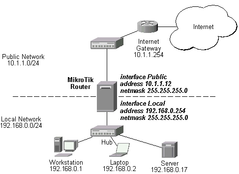
The IP addresses and routes of the MikroTik router are as follows:
[mikrotik]> ip address print
  # ADDRESS         NETMASK         NETWORK         BROADCAST       INTERFACE
  0 192.168.0.254   255.255.255.0   192.168.0.254   192.168.0.255   Local
  1 10.1.1.12       255.255.255.0   10.1.1.12       10.1.1.255      Public
[mikrotik]> ip route print
  # DST-ADDRESS     NETMASK         GATEWAY         PREF-ADDRESS    INTE...
  0 192.168.0.0     255.255.255.0   0.0.0.0         192.168.0.254   Local   D K
  1 10.1.1.0        255.255.255.0   0.0.0.0         10.1.1.12       Public  D K
  2 0.0.0.0         0.0.0.0         10.1.1.254      0.0.0.0         Public
[mikrotik]>
Two static NAT rules are required for translating the address:port - one for the incoming packets, and one for the outgoing packets:
[mikrotik]> ip firewall static-nat

[mikrotik] ip firewall static-nat> add dst-address 10.1.1.12 \
dst-netmask 255.255.255.255 dst-port 8080 protocol tcp \
direction in interface Public translate yes \
to-dst-address 192.168.0.17 to-dst-netmask 255.255.255.255 to-dst-port 80

[mikrotik] ip firewall static-nat> add src-address 192.168.0.17 \
src-netmask 255.255.255.255 src-port 80 protocol tcp \
direction out interface Public translate yes \
to-src-address 10.1.1.12 to-src-netmask 255.255.255.255 to-src-port 8080

[mikrotik] ip firewall static-nat> print
0   src-address: 0.0.0.0 src-netmask: 0.0.0.0 src-port: 0-65535
    dst-address: 10.1.1.12 dst-netmask: 255.255.255.255 dst-port: 8080
    interface: Public translate: yes direction: in protocol: tcp
    to-src-address: 0.0.0.0 to-dst-address: 192.168.0.17 to-src-netmask: 0.0.0.0
    to-dst-netmask: 255.255.255.255 to-src-port: 0 to-dst-port: 80

1   src-address: 192.168.0.17 src-netmask: 255.255.255.255 src-port: 80
    dst-address: 0.0.0.0 dst-netmask: 0.0.0.0 dst-port: 0-65535
    interface: Public translate: yes direction: out protocol: tcp
    to-src-address: 10.1.1.12 to-dst-address: 0.0.0.0
    to-src-netmask: 255.255.255.255 to-dst-netmask: 0.0.0.0 to-src-port: 8080
    to-dst-port: 0

[mikrotik] ip firewall static-nat>
From the global network, the server can be accessed at 10.1.1.12:8080.
From the local network, the server can be accessed at 192.168.0.17:80.
The server cannot be accessed at 10.1.1.12:8080 from the local network.
It is due to the fact, that the server sees request coming from its own network,
and it responds back directly, i.e., bypassing the router and the NAT rule.
Please see the further examples for enabling the use of global address 10.1.1.12:8080
for accessing the server locally.
Example of NAT with Masquerading
Since we use masquerading for the Local network 192.168.0.0/24 (see the Application Example above),
we should exclude masquerading for the server's address 192.168.0.17
and TCP port 80 by adding a rule with action 'accept' to the forward chain.
The second rule would masquerade everything else:
[mikrotik]> ip firewall rule
[mikrotik] ip firewall rule> add forward src-address 192.168.0.17/32 \
src-ports 80 protocol tcp interface Public
[mikrotik] ip firewall rule> add forward src-address 192.168.0.0/24 \
action masq interface Public
[mikrotik] ip firewall rule> print forward
0   action: accept protocol: tcp src-address: 192.168.0.17
    src-netmask: 255.255.255.255 src-ports: 80 dst-address: 0.0.0.0
    dst-netmask: 0.0.0.0 dst-ports: 0-65535 interface: Public tcp-option: all
    log: no
1   action: masq protocol: all src-address: 0.0.0.0 src-netmask: 0.0.0.0
    src-ports: 0-65535 dst-address: 0.0.0.0 dst-netmask: 0.0.0.0
    dst-ports: 0-65535 interface: Public log: no
[mikrotik] ip firewall rule>
The ftp uses TCP port 21 on the server for establishing the connection, and the server's tcp port 20 when connecting back to the client for data connections.
To translate the addresses and ports, totally four static NAT rules would be required. However, ports 20 and 21 can be grouped in a port range, and only two rules are required then:
[mikrotik] ip firewall static-nat> add dst-address 10.1.1.12 \
dst-netmask 255.255.255.255 dst-port 20-21 protocol tcp \
direction in interface Public translate yes \
to-dst-address 192.168.0.17 to-dst-netmask 255.255.255.255

[mikrotik] ip firewall static-nat> add src-address 192.168.0.17 \
src-netmask 255.255.255.255 src-port 20-21 protocol tcp \
direction out interface Public translate yes \
to-src-address 10.1.1.12 to-src-netmask 255.255.255.255

[mikrotik] ip firewall static-nat> print
0   src-address: 0.0.0.0 src-netmask: 0.0.0.0 src-port: 0-65535
    dst-address: 10.1.1.12 dst-netmask: 255.255.255.255 dst-port: 20-21
    interface: Public translate: yes direction: in protocol: tcp
    to-src-address: 0.0.0.0 to-dst-address: 192.168.0.17
    to-src-netmask: 0.0.0.0 to-dst-netmask: 255.255.255.255 to-src-port: 0
    to-dst-port: 0

1   src-address: 192.168.0.17 src-netmask: 255.255.255.255 src-port: 20-21
    dst-address: 0.0.0.0 dst-netmask: 0.0.0.0 dst-port: 0-65535
    interface: Public translate: yes direction: out protocol: tcp
    to-src-address: 10.1.1.12 to-dst-address: 0.0.0.0
    to-src-netmask: 255.255.255.255 to-dst-netmask: 0.0.0.0 to-src-port: 0
    to-dst-port: 0

[mikrotik] ip firewall static-nat>
Note, that the to-src-port and to-dst-port arguments have not be specified, and they have value '0', i.e., 'no translation' for ports.
Also, do not forget to exclude source address:ports 192.168.0.17:20-21 from masquerading, if it is used for local addresses:
[mikrotik] ip firewall rule> add forward src-address 192.168.0.17 \
src-netmask 255.255.255.255 src-ports 20-21 interface Public protocol tcp
[mikrotik] ip firewall rule> add forward action masq interface Public
[mikrotik] ip firewall rule> print forward
0   action: accept protocol: tcp src-address: 192.168.0.17
    src-netmask: 255.255.255.255 src-ports: 20-21 dst-address: 0.0.0.0
    dst-netmask: 0.0.0.0 dst-ports: 0-65535 interface: Public tcp-option: all
    log: no

1   action: masq protocol: all src-address: 0.0.0.0 src-netmask: 0.0.0.0
    src-ports: 0-65535 dst-address: 0.0.0.0 dst-netmask: 0.0.0.0
    dst-ports: 0-65535 interface: Public log: no

[mikrotik] ip firewall rule>
Example of NAT and Access from the Local Network
Let us reconsider the previous example of using NAT for ftp. To enable the local workstations 192.168.0.1...2 accessing the server on the local net using its global address 10.1.1.12:21, the network configuration should be changed. The requests to the server should appear as coming rather from another network than form it's own one. Then the 'backward' translation rules will be used too, since the packets would be sent back to the router.
To accomplish this:
The network diagram looks like follows:
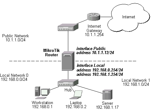
To add another address to the router, use:
[mikrotik] ip address> add address 192.168.1.24/24 interface Local
[mikrotik] ip address> print
  # ADDRESS         NETMASK         NETWORK         BROADCAST       INTERFACE
  0 192.168.0.254   255.255.255.0   192.168.0.254   192.168.0.255   Local
  1 10.1.1.12       255.255.255.0   10.1.1.12       10.1.1.255      Public
  2 192.168.1.24    255.255.255.0   192.168.1.24    192.168.1.255   Local
[mikrotik] ip address>
Add two static NAT rules:
[mikrotik] ip firewall static-nat> add dst-address 10.1.1.12 \
dst-netmask 255.255.255.255 dst-port 20-21 protocol tcp \
direction in translate yes \
to-dst-address 192.168.1.17 to-dst-netmask 255.255.255.255

[mikrotik] ip firewall static-nat> add src-address 192.168.1.17 \
src-netmask 255.255.255.255 src-port 20-21 protocol tcp \
direction out translate yes \
to-src-address 10.1.1.12 to-src-netmask 255.255.255.255

[mikrotik] ip firewall static-nat> print
0   src-address: 0.0.0.0 src-netmask: 0.0.0.0 src-port: 0-65535
    dst-address: 10.1.1.12 dst-netmask: 255.255.255.255 dst-port: 20-21
    interface: all translate: yes direction: in protocol: tcp
    to-src-address: 0.0.0.0 to-dst-address: 192.168.1.17
    to-src-netmask: 0.0.0.0 to-dst-netmask: 255.255.255.255 to-src-port: 0
    to-dst-port: 0

1   src-address: 192.168.1.17 src-netmask: 255.255.255.255 src-port: 20-21
    dst-address: 0.0.0.0 dst-netmask: 0.0.0.0 dst-port: 0-65535 interface: all
    translate: yes direction: out protocol: tcp to-src-address: 10.1.1.12
    to-dst-address: 0.0.0.0 to-src-netmask: 255.255.255.255
    to-dst-netmask: 0.0.0.0 to-src-port: 0 to-dst-port: 0

[mikrotik] ip firewall static-nat>
Add two rules to the forward chain:
[mikrotik] ip firewall rule> add forward src-address 192.168.1.17/32 \
src-ports 20-21 protocol tcp interface Public

[mikrotik] ip firewall rule> add forward action masq interface Public

[mikrotik] ip firewall rule> print forward
0   action: accept protocol: tcp src-address: 192.168.1.17
    src-netmask: 255.255.255.255 src-ports: 20-21 dst-address: 0.0.0.0
    dst-netmask: 0.0.0.0 dst-ports: 0-65535 interface: Public tcp-option: all
    log: no

1   action: masq protocol: all src-address: 0.0.0.0 src-netmask: 0.0.0.0
    src-ports: 0-65535 dst-address: 0.0.0.0 dst-netmask: 0.0.0.0
    dst-ports: 0-65535 interface: Public log: no

[mikrotik] ip firewall rule>
The local workstations form Network 0 will be accessing the server on Network 1 solely through the router, and all packets will be processed against the translation rules.
By using a DNS server, router administrators can use hostnames instead of IP addresses when setting up routes, filters, and other places where a numbered IP address is not required.
Select the DNS menu under the IP menu. The DNS box can be configured with the primary DNS and secondary DNS by selecting the DNS settings icon
. Static DNS entries have higher priority than dynamic ones that received from DNS server.ip dns menu commands:
| Command syntax | Description |
|---|---|
|
export |
Export DNS configuration and entries |
|
static |
Static DNS entries management menu |
|
set [primary-dns
<address>] |
Change DNS settings |
|
|
Show DNS settings |
ip dns static menu commands:
| Command syntax | Description |
|---|---|
|
|
Show static DNS entries |
|
export |
Export static DNS entries |
|
add name <hostname> |
Add static DNS entry |
|
find |
|
|
remove <entry number> |
Remove static DNS entry |
|
set <number> |
Change static DNS entry |
| Name in Console | Name in Java | Description |
|---|---|---|
|
primary-dns |
Primary DNS Server |
Primary DNS server address |
|
secondary-dns |
Secondary DNS Server |
Secondary DNS server address |
Static DNS parameters:
| Name in Console | Name in Java | Description |
|---|---|---|
|
name |
Name |
Host name |
|
address |
IP Address |
Host IP address |
| to the contents |
SNMPv2 (Simple Network Management Protocol version 2) is supported in limited functionality. Installation of the SNMP packages makes the router into an SNMP agent.
·
SNMPv2 support only
·
Read-only access is provided to the NMS (network management system)
·
Communities are limited to Public
·
No Trap support
Topics covered in this section:
The snmp-2.3.0.npk(less than 150KB) package for v2.3 is required. The package can be downloaded from MikroTiks web page www.mikrotik.com . To install the package, please upload it to the router with ftp and reboot. You may check to see if the SNMP package is installed with the command:
[mikrotik]> system package print
# NAME VERSION BUILD UNINSTALL
  0 routing                                          2.3.5      5     no
  1 aironet                                          2.3.5      6     no
  2 wavelan                                          2.3.5      8     no
  3 system                                           2.3.5      15    no
  4 snmp                                             2.3.5      5     no
  5 option                                           2.3.5      7     no
  6 ppp                                              2.3.5      7     no
  7 pptp                                             2.3.5      5     no
  8 pppoe                                            2.3.5      5     no
  9 radiolan                                         2.3.5      6     no
 10 ssh                                              2.3.5      7     no
[mikrotik]>
Line 4 shows that the SNMP package is installed.
When SNMP is enabled, it uses approximately 2MB of RAM. When using SNMP, memory usage estimates should be made, system resources should be monitored, and RAM should be increased accordingly.
Set [mikrotik] ip accounting set enabled yes
Example output of the print command:
[mikrotik] snmp-server> print
         enabled: yes
    contact-info: Sysadmin-555-1212
        location: MikroTik
Description of the output:
enabled - SNMP is disabled by default. Settings are enabled
yes and enabled no.
contact-info and location - Both contact-info and location
are informative only settings for the NMS.
MRTG (Multi Router Traffic Grapher) is the most commonly used SNMP monitor.
http://ee-staff.ethz.ch/~oetiker/webtools/mrtg/
Links for SNMP documentation:
http://www.cisco.com/univercd/cc/td/doc/cisintwk/ito_doc/snmp.htm
[mikrotik] snmp-server> ?
SNMP allows remote monitoring of router and statistics collecting.
  ..
  print      Show SNMP configuration
  set        Change SNMP configuration
  export     Export SNMP server configuration
[mikrotik] snmp-server> set ?
Allows to change router location and administrator contact information.
  enabled        Enable/disable SNMP service
  contact-info   Administrator contact information
  location       Router location
| to the contents |
The MikroTik RouterOS V2.3 supports the following queuing mechanisms:
The queuing can be used for limiting the bandwidth for certain IP addresses, protocols or ports. The queuing is performed for packets leaving the router through an interface. It means, that the queues should always be configured on the outgoing interface regarding the traffic flow. If there is a desire to limit the traffic arriving at the router, then it should be done at the outgoing interface of some other router.
The following topics are covered in this section:
The queue management feature is included in the "system" software package. No additional software package installation is needed for this feature.
 /ip queue add

  [ src-address a.b.c.d \ ]

  [ src-netmask a.b.c.d \ ]

  [ src-port port_range \ ]

  [ dst-address a.b.c.d \ ]

  [ dst-netmask a.b.c.d \ ]

  [ dst-port port_range \ ]

  interface name \

  [ protocol all/ggp/igmp/ip-sec/udp/egp/icmp/ip-encap/tcp \ ]

  [ queue bfifo/none/pfifo/red \ ]

  [ limit-at bandwidth \ ]

  [ max-burst burst \ ]

  [ bounded yes/no \ ]

  [ priority 1..15 \ ]

  [ weight number \ ]

  [ allot bytes \ ]

  [ bfifo-limit number \ ]

  [ pfifo-limit number \ ]

  [ red-limit number \ ]

  [ red-min-threshold number \ ]

  [ red-max-threshold number \ ]

  [ red-burst number ]
Argument description:
src-address - Source IP address. Can be in the form a.b.c.d/n:p1[-p2], that consists of the IP address, number of bits in the network mask, and the port or port range.
src-netmask - Source netmask
src-port - Source port number or range (0-65535)
dst-address - Destination IP address. Can be in the form a.b.c.d/n:p1[-p2], that consists of the IP address, number of bits in the network mask, and the port or port range.
dst-netmask - Destination netmask
dst-port - Destination port number or range (0-65535)
interface - Interface which packet leaves
protocol - Protocol
queue - Queue type (see explanation below)
limit-at - Maximum stream bandwidth (bits/s)
max-burst - Maximal number of packets allowed for bursts of packets when there are no packets in the queue. Set to '0' for no burst.
bounded - Queue is bounded. The queue can not occupy bandwidth of other queues.
priority - Flow priority (1..15)
weight - Flow weight
allot - Number of bytes allocated for the bandwidth. Should not be less than the MTU for the interface.
bfifo-limit - BFIFO queue limit. Maximum packet number that queue can hold.
pfifo-limit - PFIFO queue limit. Maximum byte number that queue can hold.
red-limit - RED queue limit
red-min-threshold - RED minimum threshold. Before this value is achieved no packets will be thrown away.
red-max-threshold - RED maximum threshold. When this value is achieved the queue will throw away the packets using maximum probability, where this probability is a function of the average queue size.
red-burst - RED burst. Number of packets allowed for bursts of packets when there are no packets in the queue. The minimum value that can be used here is equal to the value of 'red-min-threshold'.
Queue types:
You can group several networks together and have one queue for them, if a common network mask can be found for the networks. For example, networks 10.0.128.0/24 and 10.0.129.0/24 can be grouped together using a common network address/mask 10.0.128.0/22
The existing queues can be listed using the /ip queue print command. Example output is:
[mikrotik] ip queue> print
0   src-address: 0.0.0.0/0:0-65535 dst-address: 10.0.0.0/24:0-65535
    interface: developers protocol: all queue: red limit-at: 64000
    max-burst: 0 bounded: yes priority: 1 weight: 1 allot: 1536
    red-limit: 50 red-min-threshold: 12 red-max-threshold: 30
    red-burst: 20

1   src-address: 10.0.0.0/24:0-65535 dst-address: 0.0.0.0/0:0-65535
    interface: internet protocol: all queue: red limit-at: 64000
    max-burst: 0 bounded: yes priority: 1 weight: 1 allot: 1536
    red-limit: 50 red-min-threshold: 12 red-max-threshold: 30
    red-burst: 20

[mikrotik] ip queue>
For argument description see the add command above.
[mikrotik] ip queue> print
0   src-address: 0.0.0.0/0:0-65535 dst-address: 10.0.0.0/24:0-65535
    interface: developers protocol: all queue: red limit-at: 64000
    max-burst: 0 bounded: yes priority: 1 weight: 1 allot: 1536
    red-limit: 50 red-min-threshold: 12 red-max-threshold: 30
    red-burst: 20
[mikrotik] ip queue> set 0 max-burst 20
Queues are processed in the order they appear under the
/ip queue print command list. Use the /ip queue move command
to change the order of queues:
 [mikrotik] ip queue>

  move number destination
Argument description:
number - Source queue number (from print)Queues can be enabled or disabled using the /ip queue enable and /ip queue disable commands.
destination - Destination queue number (from print)
Further on, several examples of using bandwidth management are given arranged according to complexity:
Example of Emulating a 128k/64k Line
Assume we want to emulate a 128k download and 64k upload line connecting IP network 195.13.1.32/27. The network is served through the interface 'ether' of customer's router The basic network setup is in the following diagram: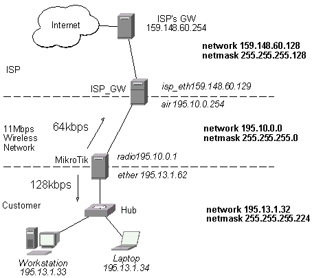
The IP addresses, routes, and masquerading firewall rule of the MikroTik router are as follows:
[MikroTik]> ip address print
  # ADDRESS         NETMASK         NETWORK         BROADCAST       INTERFACE
  0 195.10.0.1      255.255.255.0   195.10.0.1      195.10.0.255    radio
  1 195.13.1.62     255.255.255.224 195.13.1.62     195.13.1.63     ether

[MikroTik]> /ip route print
  # DST-ADDRESS     NETMASK         GATEWAY         PREF-ADDRESS    INTERFACE
  0 195.10.0.0      255.255.255.0   0.0.0.0         195.10.0.1      radio      D K
  1 195.13.1.32     255.255.255.224 0.0.0.0         195.13.1.33     ether      D K
  3 0.0.0.0         0.0.0.0         195.10.0.254    0.0.0.0         radio
It is enough to add two queues at the customer's router:
[MikroTik] ip queue>add dst-address 195.13.1.32/27 interface ether \
queue red limit-at 128000 max-burst 0 bounded yes

[mikrotik] ip queue>add src-address 195.13.1.32/27 interface radio \
queue red limit-at 64000 max-burst 0 bounded yes
Leave all other parameters as set by default. The limit is approximately 128kbps going to the client's network and 64kbps leaving the client's network. No burst of the packets is allowed. Please note, that each queue has been added for the outgoing interface regarding the traffic flow. If local address space 192.168.0.0/24 and masquerading are used for the client computers in the previous example setup, then the outgoing traffic has masqueraded source address 195.10.0.1, i.e., the outgoing packets have external address of the router as the source. The network diagram is as follows:
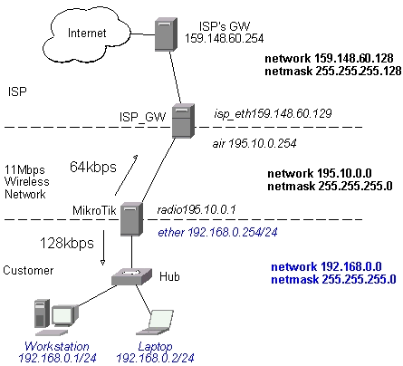
The IP addresses, routes, and masquerading firewall rule of the MikroTik router are as follows:
[MikroTik]> ip address print
  # ADDRESS         NETMASK         NETWORK         BROADCAST       INTERFACE
  0 195.10.0.1      255.255.255.0   195.10.0.1      195.10.0.255    radio
  1 192.168.0.254   255.255.255.0   192.168.0.254   192.168.0.255   ether

[MikroTik]> /ip route print
  # DST-ADDRESS     NETMASK         GATEWAY         PREF-ADDRESS    INTERFACE
  0 195.10.0.0      255.255.255.0   0.0.0.0         195.10.0.1      radio      D K
  1 192.168.0.0     255.255.255.0   0.0.0.0         192.168.0.254   ether      D K
  3 0.0.0.0         0.0.0.0         195.10.0.254    0.0.0.0         radio

[MikroTik]> /ip firewall rule print forward
0   action: masq protocol: all src-address: 192.168.0.0 src-netmask: 255.255.255.0
    src-ports: 0-65535 dst-address: 0.0.0.0 dst-netmask: 0.0.0.0 dst-ports: 0-65535
    interface: radio log: no
The queuing rule for incoming traffic should match the customer's local addresses, whereas the rule for outgoing traffic should match the router's external address as the source address:
[MikroTik] ip queue>add dst-address 192.168.0.0/24 interface ether \
queue red limit-at 128000 max-burst 0 bounded yes

[MikroTik] ip queue>add src-address 195.10.0.1/32 interface radio \
queue red limit-at 64000 max-burst 0 bounded yes
Let us assume, that for administrative purposes, we want to contact the MikroTik router without being affected by the bandwidth limitation. Then additional rule(s) having no limitation should be added before the limiting one(s). For example, we want no limitation to networks 195.10.0.0/24 and 159.148.60.128/25. The queue rules should be added as follows:
[MikroTik] ip queue>add src-address 195.10.0.1/32 dst-address 195.10.0./24 \
interface radio queue red limit-at 10000000 max-burst 0 bounded no

[MikroTik] ip queue>add src-address 195.10.0.1/32 dst-address 159.148.60.128/25 \
interface radio queue red limit-at 10000000 max-burst 0 bounded no

[MikroTik] ip queue>add dst-address 192.168.0.0/24 interface ether \
queue red limit-at 128000 max-burst 0 bounded yes

[MikroTik] ip queue>add src-address 195.10.0.1/32 interface radio \
queue red limit-at 64000 max-burst 0 bounded yes
The first two rules mean no limitation to the networks 195.10.0.0/24 and 159.148.60.128/25, whereas the second two rules limit customer's incoming and outgoing traffic, respectively.
Example of Using Masquerading and both Private and Registered Addresses
Let us assume, that the 11Mbps wireless network uses private addresses 10.0.1.0/24, and the client's network has both private addresses 192.168.0.0/24 for ordinary users and registered addresses 195.13.1.32/27 for the server and superusers. The network diagram is as follows:
When contacting hosts outside the local network the private addresses are masqueraded by the external address 195.13.1.61 of the router. The IP addresses, routes, and masquerading firewall rule of the MikroTik router are as follows:
[MikroTik]> ip address print
  # ADDRESS         NETMASK         NETWORK         BROADCAST       INTERFACE
  0 10.0.1.1        255.255.255.0   10.0.1.1        10.0.1.255      radio
  1 192.168.0.254   255.255.255.0   192.168.0.254   192.168.0.255   ether
  2 195.13.1.62     255.255.255.224 195.13.1.62     195.13.1.63     ether
  3 195.13.1.61     255.255.255.255 195.12.1.61     195.13.1.61     radio

[MikroTik]> /ip route print
  # DST-ADDRESS     NETMASK         GATEWAY         PREF-ADDRESS    INTERFACE
  0 10.0.1.0        255.255.255.0   0.0.0.0         10.0.1.1        radio      D K
  1 192.168.0.0     255.255.255.0   0.0.0.0         192.168.0.254   ether      D K
  2 195.13.1.32     255.255.255.224 0.0.0.0         195.13.1.62     ether      D K
  3 0.0.0.0         0.0.0.0         10.0.1.254      195.13.1.61     radio
  4 159.148.60.128  255.255.255.128 10.0.1.254      0.0.0.0         radio

[MikroTik]> /ip firewall rule print forward
0   action: masq protocol: all src-address: 192.168.0.0 src-netmask: 255.255.255.0
    src-ports: 0-65535 dst-address: 0.0.0.0 dst-netmask: 0.0.0.0 dst-ports: 0-65535
    interface: radio log: no
Please note, that:
[MikroTik] ip queue>add dst-address 192.168.0.0/24 interface ether \
queue red limit-at 128000 max-burst 0 bounded yes

[MikroTik] ip queue>add src-address 195.13.1.61/32 interface radio \
queue red limit-at 64000 max-burst 0 bounded yes
The first rule matches traffic going to the ordinary users on network 192.168.0.0/24 and limits them to 128kbps. The second rule matches masqueraded packets with default destination (Internet), excluding the ISP's network 159.148.60.128/25, and limits the traffic to 64kbps. Traffic originated form the router, as well as the masqueraded connections to the ISP's network, are not limited.
The minimum configuration of the ISP_GW router is given below:
[ISP_GW]> ip address print
  # ADDRESS         NETMASK         NETWORK         BROADCAST       INTERFACE
  0 10.0.1.254      255.255.255.0   10.0.1.254      10.0.1.255      air
  1 159.148.60.129  255.255.255.128 159.148.60.129  159.146.60.255  isp_eth

[ISP_GW]> /ip route print
  # DST-ADDRESS     NETMASK         GATEWAY         PREF-ADDRESS    INTERFACE
  0 10.0.1.0        255.255.255.0   0.0.0.0         10.0.1.254      air        D K
  1 159.148.60.128  255.255.255.128 0.0.0.0         159.148.60.129  isp_eth    D K
  3 0.0.0.0         0.0.0.0         159.148.60.254  0.0.0.0         isp_eth
  4 195.13.1.32     255.255.255.224 10.0.1.1        0.0.0.0         air
| to the contents |
Standard kernel routes are created when adding an address to the router and static routes are added by the user. A third type of route is created by routing protocol. For exchanging the routing information between the routers, MikroTik Router Software supports two interior routing protocols: the Routing Information Protocol (RIP) [Version 1 and Version 2] and the Open Shortest Path First (OSPF) protocol.
RIP selects the route with the lowest metric as the best route. The metric is a hop count representing the number of gateways through which data must pass through to reach its destination. To enable the exchange of routing information between two routers connected to the same network both routers should have RIP enabled on the interfaces to the network which connects them.
Managing RIP from JavaSelect the Routing menu and the RIP menu. Select the icon of the desired interface to change its RIP settings. To choose to redistribute static, connected and OSPF routes, click on the icon
.Go to the router menu by executing the command with the corresponding name from the base level. Then go to the rip menu.
| Command syntax | Description |
|---|---|
|
|
Show RIP settings |
|
interface |
Interface menu |
|
export |
Export RIP settings |
|
set [redistribute-static no|yes] |
Change RIP settings |
To set RIP for a specific interface, go to interface submenu. Here are the commands:
| Command Syntax | Description |
|---|---|
|
|
Show RIP settings for all interfaces |
|
set <interface> |
Set RIP for a specific interface |
|
find |
|
|
enable <interface> |
Enable RIP for a specific interface |
|
disable <interface> |
Disable RIP for a specific interface |
|
export |
Export RIP settings |
| Name in Console | Name in Java | Description |
|---|---|---|
|
interface |
Interface |
Interface name |
|
receive |
Receive |
Incoming RIP mode. Can be RIP1, RIP2 or both |
|
send |
Send |
Outgoing RIP mode. Can be RIP1, RIP2 or both |
|
authentication |
Authentication |
Authentication mode |
|
authentication-key |
Authentication Key |
Password string |
|
update-timer |
Update Timer |
How often the router will send routing information. Can be entered as "12h", "34m", "34s", or "12h23m3s". |
|
garbage-timer |
Garbage Timer |
When this time passes and the router doesnt receive signal from some route, router sets hop number to maximal for that route. For possible values see garbage-timer |
|
timeout-timer |
Timeout Timer |
When this time passes and the router doesnt receive signal from some route, router deletes that route. For possible values see garbage-timer |
|
metric |
Metric |
Metric used both outgoing and incoming routes (this metric is added to existing metric of route). Positive numbers greater than 0. |
OSPF is a shortest path first or link-state protocol. OSPF is an interior gateway protocol that distributes routing information between routers in a single autonomous system. OSPF chooses the least cost path as the best path. OSPF is better suited than RIP for complex networks with many routers. To enable OSPF for an interface, OSPF network with this interface network and mask. If interface has multiple logical networks all of these networks should be added as OSPF networks.
Managing OSPF from JavaSelect the Routing menu and then the OSPF menu. Four tabs can be used for configuration: Interfaces, Areas, Networks and Virtual Links. To change general OSPF settings (router ID and routes redistribution) click on the
icon under Interfaces tag. Managing OSPF from ConsoleGo to the routing ospf menu.
| Command Syntax | Description |
|---|---|
|
interface |
OSPF interfaces menu |
|
area |
OSPF areas menu |
|
network |
OSPF networks menu |
|
virtual-link |
OSPF virtual links menu |
|
set [router-id <address>] |
Change router ID (if this value is not set than the router will choose any of assigned IP addresses) |
|
|
Show router ID |
|
export |
Export OSPF settings |
OSPF interfaces menu commands:
| Command Syntax | Description |
|---|---|
|
print [detail] |
Show OSPF interfaces (you can use detailed form) |
|
set <interface> |
Change OSPF interface settings |
|
find |
|
|
export |
Export OSPF interface settings |
| Command Syntax | Description |
|---|---|
|
|
Show OSPF areas |
|
find |
|
|
export |
Export OSPF areas |
|
set <number> [name <name>] |
Change OSPF areas |
|
add area-id <address> |
Add new OSPF area |
|
remove <area name or number> |
Remove area |
| Command Syntax | Description |
|---|---|
|
|
Show OSPF networks |
|
set <number> |
Change network properties |
|
find |
|
|
add [address <address>] |
Add network |
|
remove <host number> |
Remove network |
|
comment <number> |
|
|
enable <number> |
|
|
disable <number> |
|
|
export |
Export OSPF networks |
OSPF virtual links menu commands:
| Command Syntax | Description |
|---|---|
|
|
Show virtual links |
|
set <number> |
Change virtual link properties |
|
find |
|
|
add [neighbour-id <address>] |
Add virtual link |
|
remove <link number> |
Remove virtual link |
|
comment <number> |
|
|
enable <number> |
|
|
disable <number> |
|
|
export |
Export OSPF virtual links |
| Name in Console | Name in Java | Description |
|---|---|---|
|
interface |
Interface |
Interface name |
|
area |
Area |
Area |
|
cost |
Cost |
Cost. Positive number greater than 0 |
|
priority |
Priority |
Priority. Number from 0 till 255 |
|
authentication-key |
Authentication Key |
Authentication Key |
|
retransmit-interval |
Retransmit Interval |
Retransmit Interval. Greater than 0. Default value is 5. |
|
transmit-delay |
Transit Delay |
Transit Delay. Greater than 0. Default value is 1. |
|
hello-interval |
Hello Interval |
Hello Interval. Greater than 0. Default value is 10. |
|
dead-interval |
Router Dead Interval |
Router dead interval. If the router doesnt receive an answer from the neighbor router during that time it will regard it as not functioning. Greater than 0. Default value is 40. |
| Name in Console | Name in Java | Description |
|---|---|---|
|
area-id |
Area ID |
Area ID |
|
name |
Area Name |
Area name |
|
stub |
Stub Area |
Area that has only one link outside |
|
default-cost |
Default Cost |
Cost of a default route added to a stub area. Positive number greater than 0 |
|
authentication |
Authentication |
Authentication mode |
| Name in Console | Name in Java | Description |
|---|---|---|
|
address |
Network Address |
Host address |
|
netmask |
Network Mask |
Network mask |
|
area |
Area |
Area |
| Name in Console | Name in Java | Description |
|---|---|---|
|
neighbour-id |
Neighbor ID |
The other end router ID |
|
transit-area |
Transit Area |
Transit Area |
| to the contents |
This action can be performed only in the console. The described below commands can be executed from the base level or from anywhere else if you type / before them.
Basic router setup can be done from the base level using setup command.
Set Terminal TypeTerminal setup is performed in the terminal menu.
| Command Syntax | Description |
|---|---|
|
set ansi|linux|rxvt-m|vt100| vt220|xterm|dumb|rxvt|sun|vt102|vt52 |
Set terminal type |
|
|
Show current terminal type |
|
reset |
Reset previous terminal type |
Packages are used to upgrade the router or add features. Packages should be obtained from the MikroTik web site. After rebooting the router, the packages will be installed.
Select the System menu. Information about packages is divided in two parts one about installed packages (Packages) and the other about uploaded ones (Store). Press
to refresh information, to remove uploaded package, to uninstall package and to cancel uninstall.In the console installed and uploaded packages information can be found under the system package and system store menus.
sys package menu commands:
| Command Syntax | Description |
|---|---|
|
uninstall <number> |
Uninstall package |
|
|
Show installed packages |
| Command Syntax | Description |
|---|---|
|
remove <number> |
Remove an uploaded package |
|
|
Show uploaded packages |
General packages parameters:
| Name in Console | Name in Java | Description |
|---|---|---|
|
name |
Name |
Name of the package |
|
version |
Version |
Version number of the package |
|
build |
Build Number |
Build Number |
|
uninstall |
Uninstall |
Will be uninstalled after next reboot |
The system keeps a history of the configuration changes since last boot. The history is lost when the router is rebooted. The history buttons on the Java panel (
and ) allow the user to undo and redo actions.Viewing System History from Java
Select the History menu. The system history can be viewed in the appeared History window. The information is read only. Use the buttons on the main widow to undo and redo actions. The action that is undone is marked with blue dot
.Viewing System History from Console
The system history can be viewed from the system history menu.
| Command syntax | Description |
|---|---|
|
|
Show command history |
| Name in Console | Name in Java | Description |
|---|---|---|
|
description |
History |
System history |
|
Policy |
Shows what privileges user privileges are needed to undo the changes |
User management includes adding users, removing users, setting names, access, access groups, and passwords.
User management can be performed from the Users List windows that appears after you select the Users menu. Under Groups tag click twice on a group to edit its policies.
Go to the user menu.
| Command Syntax | Description |
|---|---|
|
|
|
|
set <user number> |
Change user properties |
|
find |
|
|
add <user number> |
Add new user |
|
remove <user number> |
Remove user |
|
comment |
|
|
export |
Export PPP users |
|
group |
Groups configuration menu |
| Command Syntax | Description |
|---|---|
|
|
Print groups information |
|
set <number> [name <name>] |
Set group properties |
|
find |
|
|
add name <name> |
Add new group |
|
remove <number> |
Remove group |
|
comment <number> |
Comment group |
|
export |
Export groups settings |
| Name in Console | Name in Java | Description |
|---|---|---|
|
name |
Name |
Login name - this value cannot be changed for existing users. Can contain letters, digits, * and _ |
|
group |
Group |
Indicates the access group the user belongs to |
|
password |
Password |
List box used to change the password for current user. It conforms to standard Unix characteristics of passwords. Can contain letters, digits, * and _ |
|
Confirm |
For password confirmation |
|
|
address |
Address |
IP address/network mask to be assigned to the users dial-in client when logged in using PPP. If the remote address is specified in PPP interface settings then this address should match the specified address in order to enable client to log in |
Note user * will be used for PPP as any user
| Name in Console | Name in Java / Description |
|---|---|
|
ftp |
Ftp to the router |
|
pocily |
Manage user policies, add and remove user |
|
read |
Read router configuration |
|
ssh |
SSH to the router |
|
test |
Test network (ping, traceroute, etc.) |
|
write |
Write router configuration |
|
local |
Login to the router from console |
|
ppp |
PPP to the router |
|
reboot |
Reboot the router |
|
telnet |
Telnet to the router |
|
web |
Connect to the router via Web |
You can easily change password using this special command.
How To Change Password Using JavaIn the main menu there is an item Password. You will be prompted to enter your old password and enter new password twice. When you logout and login for the next time, you must enter the new password. The old password is lost forever.
How To Change Password Using ConsoleGo to the base level and execute the following command:
| Command syntax | Description |
|---|---|
|
password |
Change user password. |
You will be prompted to enter your old password and enter new password twice. When you logout and login for the next time, you must enter the new password. The old password is lost forever.
Systems uptime, total memory, HDD/Flash drive size, CPU type, and CPU frequency are displayed.
Viewing System Resources from Java
Select the System menu and the Resources menu. Java gives you expanded possibilities in viewing the system resources. Under the Monitor tab a window shows the utilization of systems CPU and memory usage in graphical form. Under the IRQ tab, the systems hardware IRQs and their usage are shown. Under IO tab, the systems IO memory ranges used by various devices are shown.
Viewing System Resources from Console
In the console, system resources can be viewed in the system resource menu. There are three submenu there.
| Command Syntax | Description |
|---|---|
|
|
General system information |
|
io print |
I/O port range information |
|
irq print |
Interrupt request information |
|
monitor |
Monitor CPU and Memory Usage |
General parameters:
| Name in Console | Name in Java | Description |
|---|---|---|
|
uptime |
Uptime |
Time passed from the last restart |
|
total memory |
Total Memory |
RAM the router is using |
|
cpu type |
CPU |
Central Processing Unit type |
|
cpu freq |
CPU Frequency |
Central Processing Unit frequency |
|
hdd total |
HD Total Size |
Hard Disk Drive capacity |
|
hdd free |
HD Free Space |
Free space onnHard Disk Drive |
IRQ parameters:
| Name in Console | Name in Java | Description |
|---|---|---|
|
IRQ |
IRQ Number |
IRQ Line Number (from 0 to 15) |
|
U |
Used |
Used (yes or no) |
|
Owner |
Name |
Owning device name |
I/O parameters:
| Name in Console | Name in Java | Description |
|---|---|---|
|
IO |
Used IO Memory Ranges |
Memory addresses that a device can use to send or receive data |
|
owner |
Name |
Owning device name |
System shutdown (halt), reboot, and reset controls. For most systems, it is necessary to wait approximately 30 seconds for a safe power down.
Select the System menu then the Shutdown menu. The dialog box will appear asking you whether you want to reboot or shutdown the router. Warning: after entering shutdown, it is necessary to manually restart the router.
The following commands can be executed in the system menu:
| Command syntax | Description |
|---|---|
|
reboot |
Reboot the system |
|
reset |
Reset the system. Note This command deletes all router configuration settings!!!!! New user name is admin with no password |
|
shutdown |
Halt the system. |
Set the identification name of the router.
Setting System Identity from Java
Select System menu and then Identity and enter the router name.
Setting System Identity from Console
Go to the system identity menu.
| Command Syntax | Description |
|---|---|
|
set <name> |
Set system identity |
|
|
|
|
export |
| Name in Console | Name in Java | Description |
|---|---|---|
|
<name> |
Router Name |
System identity string is used as human friendly name for router and also in SNMP queries. Maximum is 16 characters. |
View and change the system date and time settings.
Setting Date and Time from Java
Select the System menu and the Clock menu.
Setting Date and Time from Console
In the system console date and time settings can be change in two different menus. These commands can be executed from the sys date menu:
| Command syntax | Description |
|---|---|
|
set time [HH:MM:SS] |
Set system time |
|
set date [month/DD/YYYY] |
Set system date |
|
|
Shows current date and time |
Date and time settings become permanent and effect BIOS settings.
Date parameters:
| Parameter name | Description |
|---|---|
|
month |
Month should be entered using three first letters of its name |
|
day |
Day of a month |
|
year |
Year should be entered using all four digits |
Various system events and status information can be logged. Logs can be saved in a file on the router or sent to a remote server running a syslog daemon. MikroTik provides a shareware Windows Syslog daemon at MikroTik.com.
Managing System Logs from Java
Click on the System menu. If you want to view all system logs then go to the Logs menu. For configuring logs select the Log Manager menu. Select the Log Default Settings icon to set number of buffer lines, default IP address, and default port. To configure log sources select the icon of the corresponding line.
Managing System Logs from Console
Local logs can be viewed in the log menu:
| Command syntax | Description |
|---|---|
|
|
Display local log buffer |
Global logging management is performed in the system logging menu.
system logging menu commands:
| Command syntax | Description |
|---|---|
|
|
Show global logging configuration |
|
set |
Change global logging configuration |
|
export |
Export logging settings |
|
facility |
Log configuration menu |
facility submenu commands:
| Command syntax | Description |
|---|---|
|
|
Show configuration of log sources |
|
set <number> |
Change configuration of log sources |
|
find |
|
|
comment |
|
|
export |
Log facility parameters:
| Name in Console | Name in Java | Description |
|---|---|---|
|
group |
Group |
(Read-only) Name of the log group |
|
type |
Logging |
Type of logging. |
|
prefix |
Prefix |
Each line coming from this log facility is preceded by a prefix |
|
remote-address |
Remote Address |
Remote log server IP address. Used when logging type is remote. If not set, default log server IP address is used |
|
remote-port |
Remote Port |
Remote log server UDP port. Used when logging type is remote. If not set, default log server UDP port is used |
| Type | Description |
|---|---|
|
local |
When type "local" is used, logs are stored in local log buffer |
|
none |
When type "none" is used, logs from this source are discarded |
|
remote |
When type "remote" is used, logs are sent to remote log server |
Global logging parameters:
| Name in Console | Name in Java | Description |
|---|---|---|
|
buffer-lines |
Number of Buffer Lines |
Number of lines kept in local buffer. When number of lines in local log buffer is exceeded, lines from the beginning of buffer are deleted. |
|
default-remote-address |
Default IP Address |
Remote log server IP address. Used when remote logging is enabled but no IP address of the remote server is specified (IP=0.0.0.0) |
|
default-remote-port |
Default Remote Port |
Remote log server UDP port. Used when remote logging is enabled but no UDP port of the remote server is specified (UDP=0) |
You can view and set Software ID Number by executing the following commands in system license menu in console.
| Command syntax | Description |
|---|---|
|
unlock <key> |
Set new software key |
|
|
Show software ID number |
| to the contents |
MikroTik tools include standard TCP/IP tools such as ping and trace-route and also custom made tools. MikroTik custom tools are designed to assist you in verifying the quality of links stability and bandwidth. If you have any suggestion for improving these tools, please suggest it at our suggestion page on our web site.
Ping uses Internet Control Message Protocol (ICMP) Echo messages to determine if a remote host is active or inactive and to determine the round-trip delay when communicating with it.
Launching Ping Utility from Java
Select the Ping submenu in the Tools menu. The Ping utility sends four ping messages and displays them in real time in the Ping list box.
Launching Ping Utility from Console
From local console enter the command ping from the base level or us /ping from any location in the console.
| Command syntax | Description |
|---|---|
|
ping <address>
[size <packet size>] |
Send ICMP Requests |
Ping utility shows Time To Live value of the received packet (ttl) and Roundtrip time (time) in ms.
The console Ping session may be stopped when the Ctrl + C is pressed.
Ping Utility Parameter Description
| Name in Console | Name in Java | Description |
|---|---|---|
|
<address> |
Ping To |
IP address for the host you want to ping. |
|
size |
Packet Size |
(optional) Size of each ICMP packet (in bytes). |
|
interval |
Interval |
(optional) Delay between messages (in seconds). Default is 1 second. Can be set as 0.5s , 100 ms etc/ |
|
count |
(count is 4 by default) |
Console only. How many time ICMP packets will be sent. If not specified, ping continues till CTRL+C is pressed |
Traceroute is a TCP/IP protocol-based utility, which allows the user to determine how packets are being routed to a particular host. Traceroute works by increasing the time-to-live value of packets and seeing how far they get until they reach the given destination; thus, a lengthening trail of hosts passed through is built up.
Launching Traceroute Utility from Java
Select the Traceroute window in the Tools menu. When the trace is complete, the output indicates total number of hops to the host and corresponding TTL values per hop.
Launching Traceroute Utility from Console
Execute the command traceroute from the base level:
| Command syntax | Description |
|---|---|
|
traceroute <address>
[timeout <timeout>] |
Trace route to a host |
Traceroute shows the number of hops to the given host address of every passed gateway. Traceroute utility sends packets three times to each passed gateway so it shows three timeout values for each gateway in ms.
General Traceroute Utility Parameters
| Name in Console | Name in Java | Description |
|---|---|---|
|
<address> |
Trace To |
IP address of the host you are tracing route to. |
|
timeout |
Timeout |
(optional) Response waiting timeout, i.e. delay between messages. Should be less than 5s (0.5s or 100ms) |
|
port |
Port number. Values are in range 0-65535 |
|
|
tos |
Type Of Service parameter of IP packet. Values are from 0 till 7. |
|
|
size |
Packet Size |
(optional) Packet size in bytes (10..1500, default 64) |
The Bandwidth Tester can be used to monitor the throughput only to a remote MikroTik router (either wired or wireless) and thereby help to discover network bottlenecks.
The TCP test uses the standard TCP protocol with acknowledgments and follows the TCP algorithm on how many packets to send according to latency, dropped packets, and other features in the TCP algorithm. Please review the TCP protocol for details on its internal speed settings and how to analyze its behavior. Statistic for throughput are calculated using the entire size of the TCP packet. As acknowledgments are an internal working of TCP, their size and usage of the link are not included in the throughput statistics. Therefore this statistic is not as reliable as the UDP statistic when estimating throughput.
The UDP tester sends 110% or more packets than currently reported as received on the other side of the link. To see the maximum throughput of a link, the packet size should be set for the maximum MTU allowed by the links usually this is 1500 bytes. There is no acknowledgment required by UDP, this implementation means that the closest approximation of the throughput can be seen.
Select the Bandwidth submenu of the Tools menu. Designate the IP address of the host to test and choose the test mode (either TCP or UDP).
For UDP, choose the desired Packet Size in the corresponding edit box. The test output is represented as two graphs showing current speed and the ten-second average.
Use the btest command from the base level.
| Command syntax | Description |
|---|---|
|
btest <address> |
Run bandwidth test to a remote MikroTik router |
Example:
[P46]> btest 10.0.0.56 protocol udp size 50
Bandwidth test to 10.0.0.56, protocol UDP, packet size 50
To stop bandwidth test use CTRL + C.
| Name in Console | Name in Java | Description |
|---|---|---|
|
<address> |
Test link to |
IP address of destination host |
|
protocol |
TCP / UDP |
Test type can be UDP or TCP |
|
size |
Packet Size (UDP only) |
Packet size (50 to 1500 bytes) |
Ping flood sends ICMP (Internet Control Message Protocol) echo requests to a remote host in the same manner as the ping utility but it sends the next request as soon as it receives a reply.
Launching Ping Flood from Java
Select the Flood Ping submenu in Tools menu. Flood ping shows sent packets percentage (from the given number), received packages percentage, minimum, average and maximal Roundtrip Time of the packages.
Launching Ping Flood from Console
Command fping should be executed from the base level with the following parameters:
| Command Syntax | Description |
|---|---|
|
fping <address>
|
Launch flood ping |
| Name in Console | Name in Java | Description |
|---|---|---|
|
<address> |
Ping To |
IP address of destination host |
|
size |
Packet Size |
Size of each ICMP packet (in bytes) |
|
count |
Packet Count |
Number of ICMP packets |
|
interval |
Interval |
Time after which in the packet is considered lost in case of no response (must be less than 5 seconds) |
Netwatch every specified time period sends ping packets to the specified IP address and checks whether it is up or down and the time how long it is up or down.
Select the Netwatch submenu in Tools menu. Netwatch shows status of the host (up/down) and the time since which the host is up/down.
Launching Netwatch from Console
Command netwatch should be executed from the base level with the following parameters:
| Command syntax | Description |
|---|---|
|
netwatch host
<address> |
Launch netwatch |
| Name in Console | Name in Java | Description |
|---|---|---|
|
host |
Host |
IP address of destination host |
|
interval |
Interval |
After each interval the router will send 3 ping packets. If the host replies, only one ping packet is sent (seconds) |
|
timeout |
Timeout |
How long to wait the answer of the host. If three times the router wont receive an answer after timeout, the host will be considered to be down (milliseconds) |
| to the contents |
Topics covered in this section:
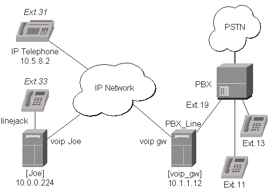
The IP Telephone System is a MikroTik Router with a Quicknet PhoneJACK
or LineJACK card connecting an analog phone.
The IP Telephony Gateway is a MikroTik Router with a Quicknet LineJACK
card connected to the Public Service Telephone Network (PSTN) or a PBX.
The MikroTik IP Telephones and IP Telephony Gateways are interoperable with the following H.323 terminals:
Please install the telephony hardware into the PC accordingly the instructions provided by card manufacturer.
If the MikroTik router will be used as
/ip telephony
The IP Telephony requires IP network connection and configuration. To receive and make IP telephone calls, at least one IP address per phone/line card should be assigned to the router. The basic IP configuration can be done under:
/ip address - for
addresses,
/ip route - for routes.
/ip telephony voice-port
The following commands are available:
/ip telephony voice-port

      print
Example output of the print command:
[mikrotik] ip telephony voice-port> print
0   name: Normunds type: linejack playback-volume: -2
    record-volume: -2 silence-detection: no
    ring-cadence: ++-++--- ++-++--- region: us jitter-buffer: 50ms
    echo-cancellation: yes aec-tail-length: short
    aec-nlp-threshold: low aec-atten-scaling: 4
    aec-atten-boost: 0

1   name: MiksTel type: linejack playback-volume: -2
    record-volume: -2 silence-detection: no
    ring-cadence: ++-++--- ++-++--- region: us jitter-buffer: 50ms
    echo-cancellation: yes aec-tail-length: short
    aec-nlp-threshold: low aec-atten-scaling: 4
    aec-atten-boost: 0
[mikrotik] ip telephony voice-port>
Description of the output:
name - name assigned to the voice port by user. The default name is PhoneJack[x] or LineJack[x] depending on the type of respective telephony card installed and its number.
type - type of the installed telephony voice port, i.e., PhoneJack or LineJack.
playback-volume - playback volume in dB, 0dB means no change, possible values are -24...24dB.
record-volume - recording volume in dB, 0dB means no change, possible values are -24...24dB.
silence-detection - if 'yes', then no audio data is sent over the IP network during the silence period.
ring-cadence - a 16-symbol ring cadence for the phone, each symbol is 0.5 seconds, '+' means ringing, '-' means no ringing.
region - regional setting for the voice port.
jitter-buffer - size of the jitter buffer, 0...1000ms. If jitter-buffer=0, the size of it is adjusted automatically.
echo-cancellation - echo detection and cancellation. Possible values are 'yes/no'.
aec-tail-length - size of the buffer of echo detection. Possible values are 'short/medium/long'.
aec-nlp-threshold - level of cancellation of silent sounds. Possible values are 'off/low/medium/high'.
aec-atten-scaling - factor of additional echo attenuation. Possible values are 0...10.
aec-atten-boost - level of additional echo attenuation. Possible values are 0, 6, 12 ... 84, 90dB, i.e., should be multipliers of 6.
 /ip telephony voice-port

      set number

      [ name new_name \]

      [ playback-volume -24...24 \]

      [ record-volume -24...24 \]

      [ silence-detection no/yes \]

      [ ring-cadence string \]

      [ jitter-buffer 0...1000ms \]

      [ echo-cancellation no/yes \]

      [ aec-tail-length short/medium/long \]

      [ aec-nlp-threshold off/low/medium/high \]

      [ aec-atten-scaling 0...10 \]

      [ aec-atten-boost 0...90 ]
For the argument description and available values see the print command above.
The jitter buffer preserves quality of the voice signal against the loss or delay of packets while traveling over the network. The larger the jitter buffer, the larger the total delay, but fewer packets lost due to timeout. If the jitter-buffer=0, then it is adjusted automatically during the conversation to minimize the number of lost packets.
/ip telephony voice-port show-stats
/ip telephony voice-port show-stats

      print number
Here, the 'number' is the number of telephony voice port, or its name. Example output of the print command:
        round-trip-delay: 5ms
            packets-sent: 1846
              bytes-sent: 443040
           max-send-time: 31ms
           avg-send-time: 30ms
           min-send-time: 29ms
        packets-received: 1843
          bytes-received: 442320
        max-receive-time: 31ms
        avg-receive-time: 30ms
        min-receive-time: 29ms
            packets-lost: 0
    packets-out-of-order: 0
        packets-too-late: 2
    average-jitter-delay: 41ms
The 'average-jitter-delay' is the approximate average time from the moment
of receiving an audio packet from the IP network till it is played back over
the telephony voice port. The value shown is never less than 30ms.
The total delay from the moment of recording the voice signal till its
playback is the sum of following three delay times:
If there is no connection at the moment, all statistics are shown as zero values.
 /ip telephony voice-port

      monitor number
Here, the 'number' is the number of telephony voice port, or its name. Example output of the monitor command:
           status: connection
             port: line
      line-status: plugged
        direction: port-to-ip
           number: *
         duration: 18s
remote-party-name: PhoneJack1 [10.0.0.224]
Description of the output:
status - status of the telephony voice port. Possible values:
'on-hook' - the handset is on-hook.
'off-hook' - the handset is off-hook and a number is being dialed.
'ring' - there is a call through the voice port. 'direction' shows the direction of the call.
'connection' - the connection has been established.
'busy' - the call is terminated, but the handset is still 'off-hook'.
port - the active port of the telephony voice port. Possible values are:
'phone' - telephone connected to the voice port (POTS port).
'line' - line connected to the LineJACK card (PSTN port).
direction - direction of the call: origoination-to-termination. Possible values:
'ip-to-port' - call from the IP network.
'port-to-ip' - call from the port to an IP address over the network.
number - the number dialed at the phone, or the number which is being dialed over the line.
duration - duration of the call, i.e., of the audio connection over the IP network.
remote-party-name - name of the QuickNet card and IP address of the remote party calling or being called.
/ip telephony outgoing
The rules are used based on the numbers dialed on the telephone or received over the line. The following commands are available:
/ip telephony outgoing

      print
Example output of the print command:
[mikrotik] ip telephony outgoing> print
  # VOICE-PORT    PHONE-NUMBER          ADDRESS         REMOTE-NUMBER
  0 MiksTel       266                   10.0.0.224
  1 MiksTel       9#######              10.5.5.247      9*
  2 Maris         266                   10.0.0.224
  3 Maris         9#######              10.5.5.247      9*
  4 MiksTel       2#                    10.5.5.244      2*
  5 Maris         2#                    10.5.5.244      2*
[mikrotik] ip telephony outgoing>
Description of the output:
# - number of the rule.
VOICE-PORT - name of the telephony voice port.
PHONE-NUMBER telephone number template for executing this rule.
ADDRESS IP address of the remote IP telephony gateway or IP telephone.
REMOTE-NUMBER telephone number to be sent over as an additional parameter to the remote IP telephony gateway.
/ip telephony outgoing

      add voice-port LineName \

      phone-number number \

      address A.B.C.D \

      [ remote-number number ]
Argument description:
voice-port specifies the telephony voice port for the rule to be applied. LineName should match the name of one of the voice ports installed, see /ip telephony voice-port print.
phone-number telephone number template for executing this rule. Available values are a number string padded with '#', or an asterisk '*'.
address IP address of the remote IP telephony gateway or IP telephone.
remote-number telephone number to be sent over as an additional parameter to the remote IP telephony gateway. This parameter can be used by the remote end as a number to be dialed.
/ip telephony outgoing

      set number

      [ voice-port LineName \ ]

      [ phone-number number \ ]

      [ address A.B.C.D \ ]

      [ remote-number number ]
For the argument description please see the add command above.
/ip telephony outgoing

      remove number
Here, the 'number' is the number of the rule as presented by the print command.
Additional information on using the phone-number and remote-number arguments.
The 'phone-number' can end with symbols '#', each of which means one digit dialed. If the argument 'phone-number' ends with symbols '#', and the 'remote-number' ends with '*', then the '*' would be substituted by the digits dialed, when sending the number to the remote host.
In case of an IP telephone system (phone connected to the LineJACK
or PhoneJACK card):
In case of an IP telephony gateway (telephone line connected to the
LineJACK card):
The following table explains, how the number sent over to the remote host is determined from the dialed number and the argument values for 'number' and 'dialed-number'.
| Dialed Number | 'number' | 'remote-number' | Sent Number |
| 91112345 | 9####### | 9* | 91112345 |
| 257 | 25# | * | 7 |
| 259 | 25# | * | 9 |
| 257 | 2## | 91 | 91 |
| 257 | 2## | empty | none |
| 257 | 257 | 6* | 6 |
| none | * | 14 | 14 |
/ip telephony incoming
The rules are used based on the IP address specified. Incoming calls are accepted at the tcp port number 1720. Only one rule per IP address is allowed! Calls from the IP network are forwarded to the voice port specified by the rule.
Following commands and submenus are available:
/ip telephony incoming

      print
Example output of the print command:
[mikrotik] ip telephony incoming> print
# ADDRESS         VOICE-PORT            PHONE-NUMBER
0 10.5.8.224      MiksTel
1 10.5.8.225      Maris
[mikrotik] ip telephony incoming>
Description of the output:
# - number of the rule
ADDRESS IP address of the router for accepting a call.
VOICE-PORT - name of the telephony voice port for the rule to be applied.
PHONE-NUMBER telephone number to be dialed, if a call is received over the IP network.
/ip telephony incoming

      add voice-port LineName \

      address A.B.C.D \

      [ phone-number number ]
Argument description:
voice-port specifies the telephony voice port for the rule to be applied. LineName should match the name of one of the voice ports installed, see /ip telephony voice-port print.
address IP address of the router for accepting a call. The address should be present under '/ip address' !
phone-number telephone number to be dialed, if a call is received over the IP network.
/ip telephony incoming

      set number

      [ voice-port LineName \ ]

      [ address A.B.C.D ]

      [ phone-number number \ ]
For the argument description please see the add command above.
/ip telephony incoming

      remove number
Here, the 'number' is the number of the rule as presented by the print command.
Additional information on using the phone-number argument.
In case of an IP telephone (phone connected to the LineJACK or PhoneJACK
card), the connected phone is being ringed on an incoming call.
In case of an IP telephony gateway (telephone line connected to the
LineJACK card):
the resulting number to be dialed is calculated using the value set for the
argument 'number' and the number received over the IP network.
The following table explains, how the resulting number is determined from the received number and the argument value for 'phone-number'.
| Received Number | 'phone-number' | Resulting Number |
| x | y* | yx |
| x | y | y |
| 75 | 2* | 275 |
| 75 | * | 75 |
| 75 | 2 | 2 |
| 75 | none | empty (rings the telephone connected to the phone port of the Phone/LineJACK card) |
| none | * | empty (rings the telephone connected to the phone port of the Phone/LineJACK card) |
| none | ** | * (the call goes into the line without any number) |
| 75 | ** | *75 (the call goes into the line, and the number "75" is dialed) |
/ip telephony codec
Available commands:
print prints the CODECs in the order they are used.CODECs are used in the order of their appearance in the list, i.e., according to the priority, number "0" being the highest one. CODECs can be enabled, disabled and moved within the list. When connecting with other H.323 systems, the protocol will negotiate the CODEC which both of them support according to the priority order.Example printout:
[mikrotik] ip telephony codec> print
# NAME
0 G.711-uLaw-hw-64k
1 G.723.1-hw-6.4k
2 G.728-hw-16k
3 GSM-06.10-sw-13.2k
4 LPC-10-sw-2.5k
enable enables CODEC under specified number or name.
disable disables CODEC under specified number or name.
move moves CODEC from one place to another.
The choice of the CODEC type is based on the throughput and speed of the network. Better audio quality can be achieved by using CODEC requiring higher network throughput. The highest audio quality can be achieved by using the G.711-uLaw CODEC requiring 64kb/s throughput for each direction of the call. It is used mostly within a LAN. The G.727.1 CODEC is the most popular one to be used for audio connections over the Internet. It requires only 6.4kb/s throughput for each direction of the call.
The IP Telephone is a MikroTik Router with a Quicknet PhoneJACK or LineJACK card connecting an analog phone.
Assume, that:
/ip telephony incoming
add voice-port PhoneJack1 \
address 192.168.0.1
/ip telephony outgoing
add voice-port PhoneJack1 \
phone-number 12 \
address 192.168.2.2
/ip telephony outgoing
add voice-port PhoneJack1 \
phone-number 9####### \
address 10.0.0.1 \
remote-number 2*
  /ip telephony voice-port
  set aec-tail-length short \
  aec-nlp-threshold low
Assume, that:
/ip telephony incoming
add voice-port LineJack1 \
address 10.0.0.1 \
phone-number **
/ip telephony outgoing
add voice-port LineJack1 \
phone-number * \
address 192.168.0.1
/ip telephony voice-port
set aec-tail-length long
The setup is described in the following diagram:
The IP Telephone is a MikroTik Router with a Quicknet PhoneJACK or LineJACK card connecting an analog phone.
We want to be able to make IP calls from one phone to other. To make a call, it should be enough to pick up the handset. It's similar to the "hot line" you have seen in movies - connecting the presidents of two countries.
Assume that:
The IP telephony configuration should be as follows:
/ip telephony incoming
add voice-port Joe address 192.168.0.1
/ip telephony outgoing
add voice-port Joe phone-number * address 192.168.2.2
/ip telephony incoming
add voice-port Mike address 192.168.2.2
/ip telephony outgoing
add voice-port Mike phone-number * address 192.168.0.1
The setup is described in the following diagram:
The IP Telephone is a MikroTik Router with a Quicknet PhoneJACK or LineJACK
card connecting an analog phone.
The IP Telephony Gateway is a MikroTik Router with a QuickNet LineJACK
card connected to the PSTN or a PBX.
We want to be able to use the IP telephone and
The IP telephony configuration should be as follows:
/ip telephony incoming
add voice-port PhoneJack1 address 192.168.0.1
/ip telephony outgoing
add voice-port PhoneJack1
phone-number ####### address 10.0.0.1 remote-number *
/ip telephony outgoing
add voice-port LineJack1 phone-number * address 192.168.0.1
/ip telephony incoming
add address 10.0.0.1 voice-port LineJack1 phone-number **
The setup is described in the following diagram:
The IP Telephony Gateway is a MikroTik Router with a QuickNet LineJACK card connected to the PBX.
We want to be able to use make calls from local telephones of one PBX to local telephones or external lines of the other PBX.
Assume that:
The IP telephony configuration should be as follows:
/ip telephony incoming
add voice-port LineJack1 address 10.0.0.1 phone-number **
/ip telephony outgoing
add voice-port LineJack1
phone-number ## address 10.2.0.1 remote-number *
/ip telephony outgoing
add voice-port LineJack2
phone-number ## address 10.0.0.1 remote-number *
add voice-port LineJack2
phone-number 9####### address 10.0.0.1 remote-number 9*
/ip telephony incoming
add address 10.2.0.1 voice-port LineJack2 phone-number **
| to the contents |
The MikroTik router can act as an ISDN client for dialing out, or as an ISDN server for accepting incoming calls. The dial-out connections may be set as dial-on-demand or as permanent connections (simulating a leased line). The remote IP address (provided by the ISP) can be used as the default gateway for the router.
The v2.3 of the MikroTik Router OS supports following ISDN adapters:
Please install the ISDN adapter into the PC accordingly the instructions provided by the adapter manufacturer.
/driver

  load driver_name

  isdn-protocol euro/german
Argument description:
driver_name - name of the driver. The list of available drivers can be obtained by entering '/driver load [Tab][Tab]'
isdn-protocol - data channel protocol, the default is 'euro'
Complete list of all supported ISDN adapters and their driver names:
Check the loaded drivers by using the '/driver print' command. Example output looks like here:
[mikrotik] driver> print
  # DRIVER                                                                 IRQ IO     MEMORY     ISD...
  0 PCI NE2000                                                                                          D
  1 HFC 2BDS0 PCI
[mikrotik] driver>
ISDN channels are added to the system automatically when the ISDN card driver is loaded. Each channel corresponds to one physical 64K ISDN data channel.
The list of available ISDN channels can be viewed using the '/isdn-channels print' command. The channels are named 'CH0', 'CH1', and so on. E.g., if you have two ISDN channels, and one of them currently used by an ISDN interface, but the other available, the output should look like this:
[mikrotik] isdn-channels> print
  # NAME DRIVER                                     CHANNEL DEVICE
  0 CH0  HiSax                                      0       isdn-out1
  1 CH1  HiSax                                      1       (unknown)
[mikrotik] isdn-channels>
ISDN channels are very similar to PPP serial ports. Any number of ISDN interfaces can be configured on a single channel, but only one interface can be enabled for that channel at a time. It means that every ISDN channel is either available or used by an ISDN interface.
In Euro-ISDN a subscriber can assign more than one ISDN number to an ISDN line. For example, an ISDN line could have the numbers 1234067 and 1234068. Each of these numbers can be used to dial the ISDN line. These numbers are referred to as Multiple Subscriber Numbers (MSN).
A similar, but separate concept is EAZ numbering, which is used in German ISDN networking. EAZ number can be used in addition to dialed phone number to specify the required service.
For dial-out ISDN interfaces, MSN/EAZ number specifies the outgoing phone number (the calling end). For dial-in ISDN interfaces, MSN/EAZ number specifies the phone number which will be answered. If you are unsure about your MSN/EAZ numbers, leave them blank (it is the default).
For example, if your ISDN line has numbers 1234067 and 1234068, you could configure your dial-in server to answer only calls to 1234068, by specifying "1234068" as your MSN number. In a sense, MSN is just your phone number.
/interface isdn-client
/interfaces isdn-client

  add \

  name interface_name \

  channel ISDN_channel \

  up \

  down \

  mtu mtu_bytes \

  mru mru-bytes \

  idle-timeout time \

  max-retries number \

  phone phone_number \

  msn number \

  dial-on-demand yes/no \

  l2-protocol hdlc/x75bui/x75i/x75ui \

  user user_name \

  add-default-route yes/no \

  local-address local_IP_address \

  remote-address remote_IP_address
Argument description:
name - Interface name
channel - ISDN channel to use
up - Enable the interface
down - Disable the interface
mtu - Maximum Transmit Unit
mru Maximum Receive Unit
idle-timeout - Idle timeout, when no activity (set to '0' to never disconnect)
max-retries - Maximum redialing retry count
phone - Phone number to dial
msn - MSN/EAZ of ISDN line provided by the line operator
dial-on-demand - Use dialing on demand
l2-protocol - Level 2 protocol to be used
user - User name that will be provided to the remote server. Information about the user has to exist in the router's user database.
add-default-route - Add default route to remote host on connect
local-address - Local IP address of interface
remote-address - Remote IP address of interface
Example of a printout of configured ISDN client interface is here:
[mikrotik] interface isdn-client> print
0   name: isdn-out1 state: up channel: CH0 mtu: 1500
    idle-timeout: 0 max-retries: 5 phone: 7542159
    msn: "" dial-on-demand: no l2-protocol: hdlc
    user: john add-default-route: yes local-address: 0.0.0.0
    remote-address: 0.0.0.0
[mikrotik] interface isdn-client>
/interface isdn-server
/interface isdn-server

  add \

  name interface_name \

  channel ISDN_channel \

  up \ down \ mtu mtu_bytes \

  mru mru_bytes \

  idle-timeout time \

  msn number \

  l2-protocol hdlc/x75bui/x75i/x75ui \

  use-pap no/yes \

  use-chap no/yes \

  local-address local_IP_address \

  remote-address remote_IP_address
Argument description:
name - Interface name
channel - ISDN channel to use
up - Enable the interface
down - Disable the interface
mtu - Maximum Transmit Unit
mru Maximum Receive Unit
idle-timeout - Idle timeout, when no activity
msn - MSN/EAZ of ISDN line provided by the line operator
l2-protocol - Level 2 protocol to be used
use-pap - Use PAP authentication
use-chap - Use CHAP authentication
local-address - Local IP address of interface
remote-address - Remote IP address of interface
Example of a printout of configured ISDN server interface is here:
[mikrotik] interface isdn-server> print
0   name: isdn-in1 state: up channel: CH0 mtu: 1500 idle-timeout: 5s
    msn: 7542159 l2-protocol: hdlc use-pap: yes use-chap: yes
    local-address: 10.99.8.1 remote-address: 10.9.88.1
[mikrotik] interface isdn-server>
Let's assume you would like to set up a router that connects your local LAN with your ISP via ISDN line. First you should load the corresponding ISDN card driver. Supposing you have an ISDN card with an HFC chip:
[mikrotik]> /driver load hfc
Now additional channels should appear. Assuming you have only one ISDN card driver loaded, you should get following:
[mikrotik]> /isdn-channels print
  # NAME DRIVER                        CHANNEL DEVICE
  0 CH0  HiSax                         0       (unknown)
  1 CH1  HiSax                         1       (unknown)
Suppose you would like to use dial-on-demand to dial your ISP and automatically add a default route to it. Also, you would like to disconnect when there is more than 30s of network inactivity. Your ISP's phone number is 12345678 and the user name for authentication is 'john'. Your ISP assigns IP addresses automatically. Add an outgoing ISDN interface and configure it in the following way:
[mikrotik]> /interface isdn-client add name isdn-isp channel CH0 phone 12345678
user john idle-timeout 30s add-default-route yes dial-on-demand yes

[mikrotik]> /interface isdn-client print
0   name: isdn-isp state: down channel: CH0 mtu: 1500 mru: 1500
    idle-timeout: 30s max-retries: 5 phone: 12345678 msn: ""
    dial-on-demand: yes l2-protocol: hdlc user: john add-default-route: yes
    local-address: 0.0.0.0 remote-address: 0.0.0.0
(If you would like to remain connected all the time, i.e., as a leased line, then set the 'idle-timeout' to 0s.)
Add the user 'john' to the router user database. Assuming that the password is 'ka28nZa!)':
[mikrotik]> /user add name john password ka28nZa!) group ppp
All that remains is to set up the interface:
[mikrotik] /interface set isdn-isp up
You can monitor the connection status with
[mikrotik] /interface isdn-client monitor isdn-isp
Let us assume you would like to set up a router for accepting incoming ISDN calls from remote clients. You have an ethernet card connected to the LAN, and an ISDN card connected to the ISDN line. First you should load the corresponding ISDN card driver. Supposing you have an ISDN card with an HFC chip:
[mikrotik] /driver load hfc
Now additional channels should appear. Assuming you have only one ISDN card driver loaded, you should get following:
[mikrotik] /isdn-channels print # NAME DRIVER ID CHANNEL 0 CH0 HiSax 0 1 CH1 HiSax 1
Add an incoming ISDN interface and configure it in the following way:
[mikrotik] /interface isdn-server
add name isdn-in1 up channel CH0 \
idle-timeout 5s msn 7542159 \
use-pap yes use-chap yes \
local-address 10.99.8.1 remote-address 10.9.88.1
[mikrotik] interface isdn-server> print
0 name: isdn-in1 state: up channel: CH0 mtu: 1500 idle-timeout: 5s
msn: 7542159 l2-protocol: hdlc use-pap: yes use-chap: yes
local-address: 10.99.8.1 remote-address: 10.9.88.1
Add user 'john' to the router user database. Assuming that the password is 'ka28nZa!)':
/user add name john password "ka28nZa!)" group ppp
Check the status of the ISDN server interface and wait for the call:
[mikrotik] interface isdn-server> print
0 name: isdn-in1 state: up channel: CH0 mtu: 1500 idle-timeout: 5s
msn: 7542159 l2-protocol: hdlc use-pap: yes use-chap: yes
local-address: 10.99.8.1 remote-address: 10.9.88.1
[mikrotik] interface isdn-server> monitor 0
uptime: 0
status: Waiting for call...
uptime: 0
status: Waiting for call...
| to the contents |
The v2.3 of the MikroTik Router OS supports the following LCD hardware:
We suggest to get the package with PC Mounting Bracket, power and serial cable for 632 LCD Module (part number PDBK632LG).
Please install the LCD module into the PC accordingly the instructions provided by the module manufacturer.
The basic installation steps should be as follows:
/system lcd
Use the /system lcd set command to configure the port and to enable or disable the LCD:
/system lcd
set \
[ enabled yes/no \]
[ port port_name ]
Argument description:
enabled - turns the LCD on or off.
port - name of the port where the LCD is connected. (Port management can be found under the /ports menu.)
Use the /system lcd print command to see the configured port and status of the LCD. Example output of the print command:
[mikrotik] system lcd> print
enabled: yes
port: serial1
[mikrotik] system lcd page> print # DISPLAY-TIME DESCRIPTION 0 5s System date and time ( 1)5s System resources- cpu and memory load ( 2)5s System uptime ( 3)5s Aggregate traffic in packets/sec ( 4)5s Aggregate traffic in bits/sec ( 5)5s Software version and build info 6 5s ether1The output of the print command shows the number, time, and short description of the displayed information items. If the item number is in parentheses, the information is not displayed. Use the enable command to enable the specified item, or the disable command to disable it.
Use the /system lcd page set command to set the display time for specified item.
/system lcd page
set number \
display-time time
Argument description:
number - number of the information item as it appears in the output of the /system lcd page print command.
display-time - display time for specified item in seconds.
Probably the selected serial port is used by PPP client or server.
Check the availability and use of the ports by examining the output of the
/port print command.
Probably none of the information display items have been enabled.
Use the /system lcd page set command to enable the display.
| to the contents |
The SSH feature can be used with various SSH Telnet clients to securely connect to and administrate the router.
The MikroTik RouterOS v2.3 supports:
The MikroTik RouterOS v2.3 has been tested with the following SSH telnet terminals:
The ssh-2.3.0.npk(less than 1MB) package for v2.3 is required. The package can be downloaded from MikroTiks web page www.mikrotik.com . To install the package, please upload it to the router with ftp and reboot. No additional settings are required. You may check to see if the SSH package is installed with the command:
[mikrotik]> system package print
# NAME VERSION BUILD UNINSTALL
0 routing 2.3.5 5 no
1 aironet 2.3.5 6 no
2 wavelan 2.3.5 8 no
3 system 2.3.5 15 no
4 snmp 2.3.5 5 no
5 option 2.3.5 7 no
6 ppp 2.3.5 7 no
7 pptp 2.3.5 5 no
8 pppoe 2.3.5 5 no
9 radiolan 2.3.5 6 no
10 ssh 2.3.5 7 no
[mikrotik]>
Line 10 shows that the SSH package is installed.
The uncompressed package will use approximately 1MB of additional Flash/HD IDE memory. A minimum amount of additional RAM is used. No hardware upgrades are suggested.
PuTTY is a free Windows (all Windows) SSH client which needs no complex installation. It is one exe file which can be downloaded and run.
Download this program from the MikroTik utilities download page or http://www.chiark.greenend.org.uk/~sgtatham/putty.html (suggested for most recent program version).
Simple instructions:
·
After downloading, run the program,
·
set the connection type to SSH,
·
On the first connection to the router a Security Alert will notify that the
servers host is no in the registry. Answer YES to trust this server.
·
The normal router login will not be display. Instead, login as: and name@xxx.xxx.xxx.xxxs
password: will appear.
No client installation is needed on all standard Linux distributions. The command: ssh l [username] [router address] will initiate a connection
Links for Windows client:
http://www.zip.com.au/~roca/ttssh.html
http://www.chiark.greenend.org.uk/~sgtatham/putty.html
http://www.massconfusion.com/ssh/
http://telneat.lipetsk.ru/
http://support.jgaa.com/?cmd=ShowArticle&ID=11
http://akson.sgh.waw.pl/~chopin/ssh/index_en.html
http://cs.mscd.edu/MSSH/index.html
http://www.networksimplicity.com/openssh/
Other links:
http://www.openssh.com/
http://www.freessh.org/
| to the contents |
The traffic accounting feature enables administrators to keep an accurate record of traffic passed through the router between IP level hosts. ISPs or network administrators can use this for traffic based billing or detailed monitoring of network activity. This feature generates simple traffic data. Additional utilities are required for useful analysis and calculation of the traffic data. Information on utilities and examples of scripts for collecting data are provided in this manual.
The MikroTik RouterOS v2.3 supports:
Topics covered in this section:
The Traffic accounting feature is included in the system package. No installation is needed for this feature.
The maximum number [threshold] of IP pairs stored may require additional RAM installation. Each IP pair uses approximately 40 bytes. The system uses a current table which accounts for current data. The system also keeps the snapshot table for retrieval. Therefore, the memory usage for the IP pairs can be calculated with number of IP pairs x 40 bytes x 2 (for the two tables). The default threshold of IP pairs is set to 1000 (80KB). When using the default threshold setting of 1000, no additional memory is suggested. For threshold settings higher than 12,500(1MB), memory usage estimates should be made, system resources should be monitored, and RAM should be increased accordingly. The maximum setting is 100,000 IP pairs.
Set [mikrotik] ip accounting set enabled yes
Example output of the print command:
[mikrotik] ip accounting> print
enabled: yes
threshold: 1000
Description of the output:
enabled - Traffic accounting is disabled by default. Settings are enabled yes and enabled no.
threshold - The threshold setting sets the maximum number of IP
pairs for the traffic accounting table see Threshold settings for more information
on the optimal settings. The default setting is for 1000 IP pairs.
Only IP traffic is accounted. As each packet passes through the router, the packet source and destination is matched to an IP pair in the accounting table and the traffic for that pair is increased. If no matching IP pair exists, a new entry to the table will be created. Both the number of packets and number of bytes are accounted. Only packets that enter and leave the router are counted. Packets that are dropped in the router are not counted. Packets that are sent from the router itself are not counted such as packets used for administration connections (i.e. web and telnet connections to the router). Packets that are masqueraded with the router will be accounted for with the actual IP hosts addresses on each side.
See Traffic Display and collection for a printout of a snapshot.
For example, a TCP connection between two computers with traffic going through the router will cause two IP pairs to be added to the traffic accounting table. One IP pair will computer A as the source and computer B as the destination. Another IP pair will have computer B as the source and computer A as the destination.
The threshold setting limits the maximum number of IP pairs in the accounting table. When the limit is reached, no new IP pairs will be added to the accounting table. Each packet that is not accounted for in the accounting table will then be added to the uncounted counter. To see if the limit on pairs has been reached, check the uncounted counter:
[mikrotik] ip accounting uncounted> print
packets: 0
bytes: 0
When a snapshot is made for data collection, the accounting table is cleared and new IP pairs and traffic data are added. The more frequently traffic data is collected, the less likelihood that the IP pairs threshold limit will be reached. It is suggested that traffic data be collected every 15 minutes.
The traffic data can be viewed by both the telnet/terminal console and java console. The traffic data can be collected manually or by using standard Unix/Linux utilities and MikroTiks shareware MT_Syslog Daemon(pending). This manual section will cover:
·
Snapshots
·
Web report setup
The traffic accounting system consist of a current accounting table and a snapshot image. When the snapshot image is made of the current accounting table, the current accounting table is cleared and starts accounting data anew. The snapshot image can made in two ways. An image of traffic data can be made manually by issuing the snapshot command from the terminal/console or java console. The shapshot can then be viewed with the print command.
The traffic data from the telnet/terminal console will appear:
[mikrotik] ip accounting snapshot> print
SRC-ADDRESS DST-ADDRESS PACKETS BYTES
10.9.5.88 10.8.0.4 408534 39822596
10.8.0.4 10.9.5.88 103944 12874447
19.11.254.136 10.0.0.144 15191 1243118 10.7.0.105 159.148.147.194 33239 2526124
159.148.147.194 10.7.0.105 33237 2526012
The web page report makes it possible to use the standard Unix/Linux tool wget to collect the traffic data and save it to a file. If the web report is enabled and the web page is viewed, the snapshot will be made when the wget (or standard browser) connection is initiated to the web page. The snapshot will then be displayed on the web page. TCP protocol used by http connections with the wget tool guarantees that none of the traffic data will be lost. The snapshot image will be made when the connection from wget is initiated. Web browsers or wget should connect to URL http://routeIP/accounting/ip.cgi
[mikrotik] ip accounting web> print
enabled: yes
address: 0.0.0.0
netmask: 0.0.0.0
For security purposes, an IP address or IP subnet can be limited to the collection of the web report. The above example of address: 0.0.0.0 and netmask: 0.0.0.0 allow all IP hosts to access the web reports. With the settings address: 10.1.0.3 and netmask: 255.255.255.255, only IP host 10.1.0.3 is allowed to access the web reports.
A simple script can be run with crond and wget to periodically collect traffic data. Timestamps can be added to the traffic data file as well as other features.
Mikrotik Download Utilities Page
There are many tools and systems to analyze traffic data. Useful common tools are:
·
Microsoft Excel
·
Grep Unix/Linux utility
·
Perl scripts
Links for documentation:
http://www.gnu.org/manual/wget/
http://www.gnu.org/manual/grep-2.4/
Command Reference
[mikrotik] ip accounting> ?
..
print Print accounting settings
set Change accounting settings
export Export accounting settings
snapshot Accounting snapshot
uncounted Uncounted packets
web Web interface settings
[mikrotik] ip accounting> set ?
enabled Enable accounting
threshold
[mikrotik] ip accounting> export ?
file File name
noresolve Do not resolve host names
[mikrotik] ip accounting snapshot> ?
..
take Take new snapshot
print Print accounting data snapshot
[mikrotik] ip accounting uncounted> ?
..
print Print information on uncounted packets
[mikrotik] ip accounting uncounted> print
packets: 0
bytes: 0
[mikrotik] ip accounting web> ?
It is possible to retrieve accounting data via www. Useful if you have script
which collects accounting data with wget unix utility
..
print Print web server configuration
set Change web server configuration
export Export web server configuration
[mikrotik] ip accounting web> print
enabled: yes
address: 0.0.0.0
netmask: 0.0.0.0
[mikrotik] ip accounting web> set ?
enabled Enable/disable web server
address Network address allowed to connect
netmask Netmask
[mikrotik] ip accounting web> export ?
file File name
noresolve Do not resolve host names
| to the contents |
MikroTik v2.3.6 (build 7) Login:Information about the version (and build) numbers of the installed MikroTik RouterOS software packages can be obtained using the /system package print command, for example:
[mikrotik]> system package print # NAME VERSION BUILD UNINSTALL 0 routing 2.3.6 6 no 1 ssh 2.3.6 7 no 2 pptp 2.3.6 5 no 3 system 2.3.6 7 no 4 ppp 2.3.6 5 no 5 pppoe 2.3.6 9 no [mikrotik]>
The list shows the number, name, version and build number of the installed software packages. If the functions provided by a software package are not required for the router implementation, the package can be marked for uninstalling at the next shutdown/reboot of the router. Use the following command to mark the packages for uninstallation:
/system package uninstall number
Here, the argument value number is the number of the package as it appears on the list of /system package print command.
If a package is marked for uninstallation, but it is required for another (dependent) package, then the marked package cannot be uninstalled. For example, the ppp package wont be uninstalled, if the pptp package is installed. You should uninstall the depended package too. For package dependencies see the section about contents of the software packages below. The system package wont be uninstalled even if marked for uninstallation.
Be careful about marking packages for uninstallation, because the only way to reverse your decision is to use the /undo command. 'Undo' works on the configuration changes in reverse order they have been performed. It means, that all configuration changes done after marking the package for uninstallation would be undone too.
[mikrotik] system store> print # NAME VERSION BUILD 0 routing 2.3.7 7 1 system 2.3.7 8 2 ppp 2.3.7 6 3 pppoe 2.3.7 10 4 pptp 2.3.7 6 [mikrotik] system store>
The installation/upgrade process is shown on the console screen (monitor) attached to the router. After successful installation the software packages are shown on the output list of the /system package print command, for example:
[mikrotik]> system package print # NAME VERSION BUILD UNINSTALL 0 system 2.3.7 8 no 1 ppp 2.3.7 6 no 2 pppoe 2.3.7 10 no 3 pptp 2.3.7 6 no 4 routing 2.3.7 7 no 5 ssh 2.3.6 7 no [mikrotik]>
Here, the list of currently installed software packages is shown including the ssh package which was nor upgraded. We recommend to upgrade all packages to the newest version.
| Name | Contents | Prerequisites | Additional License |
|---|---|---|---|
| routing | Provides RIP & OSPF support | - | - |
| snmp | Provides read only SNMP support | - | - |
| ssh | Provides remote access via SSH | - | - |
| lcd | Provides LCD monitor support | - | - |
| ups | Provides APC Smart Mode UPS support | - | - |
| ppp | Provides asynchronous PPP support | - | - |
| pptp | Provides PPTP support | ppp | - |
| pppoe | Provides PPPoE support | ppp | - |
| isdn | Provides support for ISDN | ppp | - |
| telephony | Provides IP telephony support (H.323) for Quicknet cards | - | - |
| moxa-c101 | Provides support for Moxa C101 synchronous card | - | synchronous |
| lmc-wan | Provides support for LMC synchronous cards | - | synchronous |
| cyclades | provides support for PC300 synchronous interfaces | - | synchronous |
| aironet | Provides support for CISCO Aironet IEEE 802.11 wireless PC/PCI/ISA cards | - | 2.4GHz wireless |
| arlan | Provides support for DSSS 2.4GHz 2mbps Aironet ISA cards | - | 2.4GHz wireless |
| wavelan | Provides support for Lucent WaveLAN IEEE 802.11 wireless cards | - | 2.4GHz wireless |
| teletronics | Provides support for Teletronics IEEE 802.11 wireless cards | - | 2.4GHz wireless |
| radiolan | Provides support for 5.8GHz RadioLAN ISA cards | - | radiolan |
If additional license is required to enable the functionality of a software package, the license should be obtained for the Software ID of your system. The the new key should be entered using the /system license unlock command, for example:
[mikrotik] system license> print Software ID: TPNG-SXN [mikrotik] system license> unlock D45G-IJ6-QM3 [mikrotik] system license>
The router should be rebooted to enable the functionality after entering a new license. If there is no appropriate license, the appropriate interfaces wont show up under the interface list, even though the packages can be installed on the MikroTik RouterOS and corresponding drivers loaded.
| Name | Memory (RAM) usage, MB | Storage (HDD) usage, MB |
|---|---|---|
| system | 15.2 | 12.0 |
| routing | 1.4 | 1.3 |
| snmp | 0.9 | 0.5 |
| ssh | 2.0 | 1.2 |
| lcd | 2.4 | 0.2 |
| ups | 0.8 | 0.3 |
| ppp | 1.4 | 1.0 |
| pptp | 2.1 | 1.4 |
| pppoe | 2.0 | 1.5 |
| isdn | 2.5 | 1.2 |
| telephony | 8.8 | 9.1 |
| moxa-c101 | 1.4 | 0.2 |
| lmc-wan | 0.9 | 0.2 |
| cyclades | 1.1 | 0.2 |
| aironet | 1.0 | 0.3 |
| arlan | 0.9 | 0.2 |
| wavelan | 1.4 | 0.3 |
| teletronics | 1.4 | 0.2 |
| radiolan | 1.5 | 0.25 |
| to the contents |
18. UPS monitor
Document revision 3-August-2001
Overview The UPS monitor feature works with APC UPS units that support smart signaling. This feature enables the network administrator to monitor the UPS and set the router to gracefully handle any power outage with no corruption or damage to the router. The basic purpose of this feature is to ensure that the router will come back online after an extended power failure. To do this, the router will monitor the UPS and set itself to hibernate mode when the utility power is down and the UPS battery is has less than 10% of its battery power left. The router will then continue to monitor the UPS (while in hibernate mode) and then restart itself after when the utility power returns. If the UPS battery is drained and the router loses all power, the router will power back to full operation when the utility power returns. The UPS monitor feature on the MikroTik RouterOS v2.3 support:
Topics covered in this manual:
UPS monitor installation The ups-2.3.9.npk(less than 100KB) package for v2.3 is required. The package can be downloaded from MikroTiks web page www.mikrotik.com . To install the package, please upload it to the router with ftp and reboot. You may check to see if the UPS package is installed with the command: [rack1u]> sys package print # NAME VERSION BUILD UNINSTALL 0 routing 2.3.9 13 no 1 ppp 2.3.9 12 no 2 pptp 2.3.9 12 no 3 ssh 2.3.9 15 no 4 system 2.3.9 16 no 5 aironet 2.3.9 13 no 6 lcd 2.3.9 9 no 7 pppoe 2.3.9 15 no 8 ups 2.3.9 19 no Line 8 shows that the UPS package is installed. UPS setup Check the port menu to find a free serial port. [Intnl-PBX-GW] port> print 0 name: serial0 used-by: "" baud-rate: 9600 data-bits: 8 stop-bits: 1 parity: none flow-control: none 1 name: serial1 used-by: "" baud-rate: 9600 data-bits: 8 stop-bits: 1 parity: none flow-control: none (see the port manual for more information on asynchronous ports) Connect the proprietary APC UPS smart-mode cable to Set the serial port that is connected to the APC UPS. [Intnl-PBX-GW] system ups> set port [tab][tab] serial0 serial1 [Intnl-PBX-GW]> system ups set port serial1 Where serial1 is the port that the UPS is connected toNo client installation is needed on all standard Linux distributions. The command: ssh l [username] [router address] will initiate a connection Hardware resource usage A minimum amount of hardware resources are used. UPS features Explanation of the following. set Commands: port select the serial port that the UPS is connected to using the set port command: [Intnl-PBX-GW] system ups> set port [tab][tab] moxaA1 moxaA3 moxaA5 moxaA7 serial0 moxaA2 moxaA4 moxaA6 moxaA8 serial1 [Intnl-PBX-GW] system ups> set port serial1 off-line-timeWhen set to a number >0, the router wait x hours/minutes/seconds and then go into hibernate mode until the UPS reports that the utility power is back. When set to 0, the router will go into hibernate mode according the min-run-time setting and 10% of battery power event. The default is set to 0. In this case, it will wait until the UPS reports that the battery power is below 10%. The number setting should be followed by h for hours, m for minutes, and s for seconds. [Intnl-PBX-GW] system ups> set off-line-time 4m min-run-timeAfter a utility failure, the router will monitor the run-time-left value. When the value reaches the min-run-time value, the router will go to hibernate mode. If the min-run-time value is set to 0, then the router will go to hibernate mode when the battery low signal is sent indicating that the battery power is below 10%. alarm-settingUPS sound alarm setting rtc-alarm-settingUPS sound alarm setting during run time calibration run-time-calibrationcauses the UPS to start a run time calibration until less than 25% of full battery capacity is reached. This command calibrates the returned run time value. The test begins only if battery capacity is 100%. Basic information may be obtained from the print command: [Intnl-PBX-GW]> system ups print enabled: yes port: APC off-line-time: 0 min-run-time: 0 alarm-setting: immediate-alarm rtc-alarm-setting: immediate-alarm model: SMART-UPS 1000 version: 60.11.I serial: QS0030311640 manufacture-date: 07/18/00 nominal-battery-voltage: 24 Model Less than 32 ASCII character string consisting of the UPS model name (the words on the front of the UPS itself). versionThe first field is an SKU number. The second field is a variable length decimal number indicating the firmware revision. The third field is one of the following country codes: I = 220/230/240 Vac D = 115/120 Vac A = 100 Vac M = 208 Vac J = 200 Vac Examples: 11.12.D 1.4.A 102.56.J serialA string of at least 8 characters directly representing the UPS's serial number as set at the factory. Newer Smart‑UPS models have 12-character serial numbers. manufacture-daterepresents the UPS's date of manufacture in the format " mm/dd/yy" (month, day, year). nominal-battery-voltagea three-digit number representing the UPS's nominal battery voltage rating. This is not the UPS's actual battery voltage, for example, the UPS returns "024" for a 24 Volt battery system, "018" for a 18 Volt battery system, and "048" for a 48 Volt battery system. The monitor command displays changing information: [Intnl-PBX-GW]> system ups monitor on-line: yes on-battery: no run-time-left: 26m battery-charge: 100 battery-voltage: 27 line-voltage: 230 line-frequency: 50 output-voltage: 230 load: 49Explanation of output and possible output: low-batteryappears when a low-battery event occurs on-linedisplayed when power is being provided by the external utility (power company) on-batterydisplayed when UPS battery is supplying power transfer causeOnly shown when the unit is on-battery. Displays the reason for the most recent transfer to on-battery operation, which may be: - unacceptable utility voltage rate of change. - detection of high utility voltage. - detection of low utility voltage. - detection of a line voltage notch or spike. - transfer in response to battery-test or run-time-calibration replace batteryOnly shown when the UPS report this status overloaded-outputOnly shown when the UPS report this status smart-boost-modeOnly shown when the UPS report this status smart-ssdd-modeOnly shown when the UPS report this status run-time-calibration-runningOnly shown when the UPS report this status run-time-leftthe UPS's estimated remaining run time in minutes. You can query the UPS when it is operating in the on-line, bypass, or on-battery modes of operation. The UPS's remaining run time reply is based on available battery capacity and output load. battery-chargethe UPS's remaining battery capacity as a percent of the fully charged condition. battery-voltagethe UPS's present battery voltage. The typical accuracy of this measurement is ±5% of the maximum value of 24 Vdc, 34 Vdc or 68 Vdc (depending upon the UPS's nominal battery voltage). load powerthe UPS's output load as a percentage of full rated load in Watts. The typical accuracy of this measurement is ±3% of the maximum of 105%. load-currentthe true rms load current drawn from UPS. The typical accuracy of this measurement is ±7.5% of the load rating of UPS. apparent-load-powerrepresenting the UPS's output load as a percentage of the full rated load in Volt-Amps. The typical accuracy of this measurement is ±5% of the maximum of 105%. temperaturethe UPS's present internal operating temperature in degrees Celsius. The typical accuracy of this measurement is ±5% of the full scale value of 100°C. line-frequencyWhen operating on-line, the UPS's internal operating frequency is synchronized to the line within variations within 3 Hz of the nominal 50 or 60 Hz. The typical accuracy of this measurement is ±1% of the full scale value of 63 Hz. UPS cable The APC UPS smart mode requires a special serial cable. If no cable came with the UPS, a cable may be ordered from APC or one can be made from the following. The follow diagram shows the cable for the ACP SMART-UPS and APC BACK-UPS: Female 9-pin router side Male 9-pin UPS side 1--------------------------------------------------------5 3--------------------------------------------------------1 2--------------------------------------------------------2 5--------------------------------------------------------4 8--------------------------------------------------------6 Additional resources
http://www.ibiblio.org/pub/Linux/docs/HOWTO/other-formats/html_single/UPS-HOWTO.html MikroTik Neighbor Discovery Protocol- MNDPThis document applies to MikroTik RouterOS V2.4
Overview The MikroTik Neighbor Discovery Protocol [MNDP] eases configuration and management by enabling each MikroTik router to discover other connected MikroTik routers and learn information about the system and features which are enabled. The MikroTik routers can then automatically use set features with minimal or no configuration. MNDP features:
Topics covered in this manual:
MikroTik Discovery Protocol installation on the MikroTik RouterOS v2.4 The MikroTik Discovery Protocol feature is included in the system package. No installation is needed for this feature. Hardware resource usage There is no significant resource usage. MikroTik Neighbor Discovery Protocol description MNDP basic function is to assist with automatic configuration of features that are only available between two MikroTik routers. Currently this is used for the Packet Packer feature. The Packet Packer may be enabled on a per interface basis. The MNDP protocol will then keep information about what routers have enabled the unpack feature and the Packet Packer will be used for traffic between these routers. The MikroTik routers must be connected by an Ethernet like interface. Specific Properties:
MikroTik Neighbor Discovery Protocol setup Set [MikroTik_AC] > interface set Local219 discover=yes Example output of the print command: [MikroTik_AC] ip neighbor interface> print Flags: X - disabled, D - dynamic # NAME DISCOVER 0 bridge1 yes 1 ether1 yes 2 Local219 yes To see features of neighbor routers: [MikroTik_AC] ip neighbor> print # INTERFACE ADDRESS MAC-ADDRESS UNPACKING AGE 0 Local219 10.5.8.230 00:E0:29:64:C8:76 yes 45s [MikroTik_AC] ip neighbor> Description of the output:
INTERFACE local interface to which the
neighbor is connected MikroTik Packet Packer Protocol- M3P
Document revision 30-Aug-2001
Overview The MikroTik Packet Packer Protocol [M3P] optimizes the bandwidth usage of links using protocols that have a high overhead per packet transmitted. The basic purpose of this protocol is to better enable wireless networks to transport VoIP traffic and other traffic that uses small packet sizes of around 100 bytes. M3P features:
Topics covered in this manual:
MikroTik Packet Packer Protocol installation on the MikroTik RouterOS v2.4 The MikroTik Packet Packer Protocol feature is included in the system package. No installation is needed for this feature. Hardware resource usage There is no significant resource usage. MikroTik Packet Packer Protocol description The wireless protocol 802.11 and, to a lesser extent, Ethernet protocol have a high overhead per packet because for each packet it is necessary to access the media, check for errors, resend in case of errors, and send network maintenance messages (network maintenance is only for wireless). The MikroTik Packet Packer Protocol improves network performance by aggregating many small packets into a big packet, thereby minimizing the network per packet overhead cost. The M3P is useful when the average packet size is 50-300 bytes the common size of VoIP packets. Specific Properties:
MikroTik Packet Packer Protocol setup Set [MikroTik_AC] > ip packing Example output of the print command: [MikroTik_AC] ip packing> print expected-size: 28 max-size: 500 aggregated-size: 1000 enable-unpacking: yes [MikroTik_AC] ip packing> To see interface settings: [MikroTik_AC] ip packing interface> print Flags: X - disabled # INTERFACE 0 X bridge1 1 X ether1 2 X Local219 3 wireless [MikroTik_AC] ip packing interface> Description of the output:
expected-size the average size packet
you expect for aggregation, ie. if your VoIP generates 100 byte packets this
would be the expected size. This is
used by the protocol to determine if it should wait for another packet to
complete the aggregated packet determined by the aggregated-size setting
or send an aggregated packet immediately even though it has not reached the
size of the aggregated-size setting. Copyright 2001, MikroTik |