An Interface is physical or virtual device which provides a connection to an external network. Network interfaces are created automatically when the Network Interface Card driver is loaded. Virtual (software) interfaces can be created manually.
Managing Network Interfaces from Java
Select the "Interfaces" menu to open the interface list window. The interfaces list displays basic interface parameters. Interface type specific parameters can be changed from interface details windows (opened by double clicking on icon to the left from interface name). The Interface details window has a standard "Traffic" tab which displays traffic that enters and leaves router through the interface. It can also contain other tabs with interface type specific parameters.
The Interfaces list window also contains a "blink" button. Selecting this button causes traffic to be generated on the highlighted interface and therefore blink the LEDs (light emitting diodes) on the card so that an administrator can determine which Interface name corresponds to the actual interface (when there are multiple interfaces of the same type). Some interfaces must have an Ethernet cable connected before the lights will blink. Note that not all interfaces support this function.
Managing Network Interfaces from Console
Network interface commands and submenus are located in the "interface" menu. It contains several commands that are common to all interfaces:
| Command syntax | Description |
|---|---|
| Show interface summary | |
| set [enable] [disable]
<interface number> [name <new name>] [mtu <MTU>] |
Change basic interface properties and/ or enable or disable it |
| find [from] [name] [mtu] [up][down] | |
| export [file <name>] [noresolve] | |
| blink <interface number> | Generate traffic to blink LEDs |
| monitor-traffic <interface number> | Monitor traffic on interface |
Whre <interface> is interface name or number obtained from "print" command.
The "interface" menu also contains device type specific submenus with device type specific commands. The following device type submenus can be available, depending on what features are licensed for a particular installation:
| Submenu | Description |
|---|---|
| ethernet | Ethernet interfaces |
| ppp | Async PPP interfaces |
| synchronous | Moxa Sync interfaces |
| pptp-client | PPTP dial-out interfaces |
| pptp-server | PPTP server connections |
| bridge | Bridge interface |
| arlan | Arlan IC2200 interfaces |
| radiolan | RadioLAN interfaces |
| wavelan | WaveLAN IEEE 802.11 interfaces |
| pc | Aironet 35/45/4800 interfaces |
| samsung | Samsung IEEE 802.11 interfaces |
Basic Interface Parameter Description
| Name in Console | Name in Java | Description |
|---|---|---|
| name | Name | Human friendly name for the interface. Maximum 31 character. |
| enable | Enbled (yes) | Enable interface |
| disable | Enabled (no) | Disable interface |
| mtu | MTU | Maximum Transfer Unit (in bytes) |
| arp | ARP | Address Resolution Protocol Settings |
|
disabled
|
Disable ARP protocol, use only static ARP entries | |
|
enabled
|
Enable ARP protocol for an interface (send ARP requests and replies) | |
|
proxy-arp
|
Enable ARP protocol for an interface and also reply on ARP requests about IP addresses for which the router is a gateway |
Ethernet interfaces include standard 10/100 Mbit Ethernet network interface. Ethernet interfaces do not have any device type dependent parameters. Each Ethernet interface has its MAC-address (Medium Access Control).
Managing Ethernet Interfaces from Java
Ethernet interface parameters can be changed from interface list window or from interface details window "General" tab.
Managing Ethernet Interfaces from Console
Ethernet interface management is done in submenu "interface ether".
| Command syntax | Description |
|---|---|
| print [<interface>] | Show interface(s) information |
| set <interface>
[enable] [disable] [name <new name>] [mtu <MTU>] [arp disabled|enabled|proxy-arp] |
Change interface properties |
| find | |
| export |
Where <interface> is interface name or number obtained from "print" command.
| Name in Console | Name in Java | Description |
|---|---|---|
| enable/ disable | Enabled (yes/ no) | Set Ethernet interface up or down |
| mtu | MTU | Maximum Transfer Unit. Maximum packet size to be transmitted |
| arp | ARP | Address Resolution Protocol Settings |
|
mac-address
|
MAC Address | Medium Access Control Address |
PPP (or Point-to-Point Protocol) provides a method for transmitting datagrams over serial point-to-point links. The 'com1' and 'com2' ports from standard PC hardware configurations will appear as 'serial0' and 'serial1' automatically. It is possible to add thirty-two additional serial ports with the Moxa C168 PCI multiport asynchronous card (eight ports each) to use the router for a modem pool.
To add PPP server interface, you have to choose "Interfaces" and click "Add
New" ![]() . Then choose PPP
Server and set all PPP server settings. When next time you want to change PPP
server settings or check out status or traffic of the PPP server you have to
double click on PPP server interface you added in the Interfaces list.
. Then choose PPP
Server and set all PPP server settings. When next time you want to change PPP
server settings or check out status or traffic of the PPP server you have to
double click on PPP server interface you added in the Interfaces list.
Managing PPP Server from Console
PPP server management is done in the submenu "interface ppp-server".
| Command syntax | Description |
|---|---|
| Show interface(s) information | |
| set <interface>
[enable] [disable] [name<new name>] [mtu <MTU>] [mru <MRU>] [port-id <id>] [pap no|yes] [chap no|yes] [ms-chap no|yes] [ms-chapv2 no|yes] [encryption none|optional|required| stateless] [ring-count <rings>] [idle-timeout <time>] [null-modem <on|off>] [modem-init <string>] [local-address <address>] [remote-address <address>] |
Change interface properties |
| find | |
| export | |
| monitor <interface> | Monitor interface status in real time |
Where <interface> is interface name or number obtained from "print" command.
Managing PPP Client from JAVA
To add PPP client interface, you have to choose "Interfaces" and click "Add
New" ![]() . Then choose PPP
Client and set all PPP client settings. When next time you want to change PPP
client settings or check out status or traffic of the PPP client you have to
double click on PPP client interface you added in the Interfaces list.
. Then choose PPP
Client and set all PPP client settings. When next time you want to change PPP
client settings or check out status or traffic of the PPP client you have to
double click on PPP client interface you added in the Interfaces list.
Managing PPP Client from console
PPP server management is done in the submenu "interface ppp-server".
| Command syntax | Description |
|---|---|
| Show interface(s) information | |
| set <interface> [enable] [disable] [name<new name>] [mtu <MTU>] [mru <MRU>] [port-id <id>] [pap no|yes] [chap no|yes] [ms-chap no|yes] [ms-chapv2 no|yes] [user <name>] [encryption none|optional|required| stateless] [tone-dial <enable|disable>] [dial-on-demand <enable|disable>] [add-default-route <address>] [phone <number>] [idle-timeout <time>] [null-modem <on|off>] [modem-init <string>] [local-address <address>] [remote-address <address>] [use-peer-dns <enable|disable>] |
Change interface properties |
| find | |
| export | |
| monitor <interface> | Monitor interface status in real time |
| Name in Console | Name in Java | Description |
|---|---|---|
| mtu | MTU | Maximum Transfer Unit. Maximum packet size to be transmitted |
| mru | MRU | Maximum Size of received packets |
| pap/ms-chap/ chap/ms-chapv2 | Authentication Allow | Authentication protocol type |
| encryption | Encryption | Which encryption to use. |
|
none
|
none | No encryption is used. If the other end supports compression, it will be used |
|
optional
|
optional | If the other end supports encryption, it will be used |
|
required
|
required | Encryption is required, without it connection won't be established |
|
stateless
|
stateless | Stateless-MPPE is required. Router will use MPPE-128bit or MPPE-40bit depending on the other end of connection. In stateless mode password will be changed before every packet is transmitted |
| user | User | User name to use to log into server when dialing out. Can contain letters, digits, "@", "-",".", or be "*" |
| phone | Phone Number | Phone number to call when dialing out |
| tone-dial | Tone Dial | Enable/Disable tone dial |
| ring-count | Rings | Number of rings to wait before answering phone |
| null-modem | Null Modem | Enable/Disable null-modem mode (when enabled, no modem initialization strings are sent). Default value is "on" (for COM1 and COM2 only). So by default null-modem is turned on. |
| dial-on-demand | Dial On Demand | Enable/Disable dial on demand |
| idle-timeout | Idle Time | Idle time after which close connection |
| modem-init | Modem Init | Modem Initialization String |
| add-default-route | Add Default Route | Add PPP remote address as a default route. Other settings are: destination=0.0.0.0 netmask=0.0.0.0 interface=ppp, preferred source=0.0.0.0 |
| local-address | Local Address | Local IP Address |
| remote-address | Remote Address | Remote IP Address |
Overview
PPP (point to point protocol) authentication on the MikroTik RouterOS is supported by a local authentication database or a RADIUS client. Authentication is supported for PPP asynchronous connections, PPPoE, PPTP, and ISDN PPP (local only). Authentication protocols supported are PAP, CHAP, and MS-CHAPv2. The authentication process is as follows: PPP sends a user authentication request, the user ID is first checked against the local user database for any users which have the PPP attribute, if no matching user is found then the RADIUS client (if enabled) will request authentication from the RADIUS server. Note that the users will first be checked against the local database and then only against the RADIUS server. Be careful not to have the same user with PPP on the local database and the RADIUS server the authentication will finish at the local database in this case.
Topics covered in this section:
PPP authentication and accounting installation on the MikroTik RouterOS v2.3
The local authentication and local accounting features are included in the system package. The RADIUS client and RADIUS accounting features are included in the PPP package. Note, PPP features require that the PPP package be installed.
Hardware resource usage
No significant hardware resource usage.
Local authentication overview
Local PPP authentication is part of the general user database stored on the router this database is also responsible for administration authentication for the router. Certain PPP specific attributes are supported for PPP user entries.
·
PPP remote address set from RADIUS server
·
Time limit of connections set from RADIUS server
·
MAC address (PPPoE) or remote client address (PPTP) reported
to RADIUS server
·
System identity
·
Traffic accounting (PPP style no IP pairs)
Local authentication management of PPP users
Only users which are in a group with the PPP attribute can be authenticated for PPP access. To add a user:
[mikrotik] user> add name client2 password ctest group ppp
[mikrotik] user> print
0   ;;; system default user
    name: admin group: full address: 0.0.0.0 netmask: 0.0.0.0 caller-id: ""
    only-one: no max-session-time: 0
1   name: client2 group: ppp address: 0.0.0.0 netmask: 0.0.0.0 caller-id: ""
    only-one: no max-session-time: 0
Descriptions of settings:
full address: 0.0.0.0 netmask: 0.0.0.0
This is used to determine the address to be given to the remote site, if full address is set to a specific IP (for example: full address: 10.25.0.3 netmask: 255.255.255.255), then only 10.25.0.3 will be given to the remote site. If the remote site will not accept this, then the connection will fail. If a subnet were set (for example: full address: 10.25.0.3 netmask: 255.255.255.240), then an address in the subnet 10.25.0.0/28 would be allowed if the server gives an address in that range or the server has no addresses set to give, and the client request an address in that range. If no specific address or subnet is given (for example: full address: 0.0.0.0 netmask: 0.0.0.0.), then an address from the PPP server setup of remote-address-from and remote-address-to will be given.
caller-id: ""For PPTP, this may be set the IP address which a client must connect from in the form of a.b.c.d. For PPPoE, the MAC address which the client must connect from can be set in the form or xx:xx:xx:xx:xx:xx. When this is not set, there are no restrictions on from where clients may connect.
only-one: no
If this is set to yes, then there may be only one connection at a time.
max-session-time: 0
If set to >0, then this is the max number of seconds this session can stay up. 0 indicates no session limit.
Local accounting of PPP users
To enable local authentication and accounting, set [mikrotik] ip ppp> set accounting yes authentication local. If the authentication is set to radius, then no local accounting logs will be made. The following is an example of the local accounting when a PPPoE connection is made to the PPPoE server (access concentrator).
[mikrotik]> log print
apr/04/2001 17:19:14 pppoe-in7:
waiting for authentication
apr/04/2001 17:19:14 pppoe-in7: test logged in
apr/04/2001 17:19:14 pppoe-in7: connection established
apr/04/2001 17:19:20 pppoe-in7: using encoding - none
apr/04/2001 17:25:08 pppoe-in7: connection terminated by peer
apr/04/2001 17:25:08 pppoe-in7: modem hanged up
apr/04/2001 17:25:08 pppoe-in7: connection terminated
apr/04/2001 17:25:08 pppoe-in7: test logged out, 354 4574 1279 101 83
The last line is the accounting which is printed when the connection is terminated. This line indicates that the user test connection has terminated at apr/04/2001 17:25:08. The numbers following the test logged out entry represent the following:
354 session connection
time in seconds
4574 bytes-in (from client)
1279 bytes-out (to client)
101 packets-in (from client)
83 packets-out (to client)
RADIUS Overview
RADIUS authentication gives the ISP or network administrator the ability to manage PPP user access and accounting from one server throughout a large network. The MikroTik RouterOS has a RADIUS client which can authenticate for PPP, PPPoE, and PPTP connections no ISDN remote access support currently. Features supported:
·
PPP remote address set from RADIUS server
·
Time limit of connections set from RADIUS server
·
MAC address (PPPoE) or remote client IP address (PPTP) reported
to RADIUS server
·
System identity
·
Traffic accounting (PPP style no IP pairs)
RADIUS client setup
Set [mikrotik] ip ppp> set authentication radius auth-server 10.10.1.1 shared-secret users
Example output of the print command:
[mikrotik] ip ppp> pr
            primary-dns: 159.148.60.3
          secondary-dns: 0.0.0.0
         authentication: radius
            auth-server: 10.10.1.1
          shared-secret: users
             accounting: no
        accounting-port: 1646
    authentication-port: 1645
Description of the output:
Pimary-dns ppp setting for remote site
Secondary-dns ppp setting for remote site
authentication Can be set to radius or local
auth-server IP address of the server in a.b.c.d
shared-secret corresponding text string from RADIUS server
accounting enable by setting yes or no
accounting-port default port 1646 according to RFC
authentication-port default port 1645 according to RFC
RADIUS parameters
Authentication data sent to server Data received from server Accounting information sent to server:
PW_SERVICE_TYPE       = PW_FRAMED
PW_FRAMED_PROTOCOL    = PW_FRAME_PPP
PW_NAS_IDENTIFIER     = system identity
PW_NAS_IP_ADDRESS     = local PPP interface address
PW_NAS_PORT           = unique PPP port identifier number
PW_NAS_PORT_TYPE      = async or virtual in number form
PW_CALLING_STATION_ID = for PPTP, remote IP reported
                for PPPoE, remote MAC reported
                in form of xx:xx:xx:xx:xx:xx
Data received from serve:
PW_ACCT_INTERIM_INTERVAL  = if non-zero then interval to update accouting data in seconds
PW_FRAMED_IP_ADDRESS      = PPP remote address
PW_IDLE_TIMEOUT           = if no traffic in that time, connection is closed
PW_SESSION_TIMEOUT        = connection time allowed
Accounting information sent to server:
PW_USER_NAME
PW_ACCT_INPUT_OCTETS      = octets signifies bytes
PW_ACCT_INPUT_PACKETS
PW_ACCT_OUTPUT_OCTETS
PW_ACCT_OUTPUT_PACKETS
ACCT_SESSION_TIME   = in the form of seconds
RADIUS servers suggested
Our RADIUS CLIENT should work well with all RFC complient servers. Our software has been tested with:
PPPoE bandwidth setting
This feature is currently available only version 2.4RC (release candidate). For local authentication,
this can be set in the [MikroTik] user> menu with the baud-rate value (identical to bits/s).
For Radius authentication, the account of each user in the radius server should be set with:
Paramater: Ascend-Data-Rate (with parameter ID 197 -- in bits/s)
Additional Resource
Links for SNMP documentation:
http://www.ietf.org/rfc/rfc2138.txt?number=2138
http://www.ietf.org/rfc/rfc2138.txt?number=2139
http://www.livingston.com/tech/docs/radius/introducing.html
- 3707
|
MOXA C101 Synchronous 5Mb/s AdapterDocument revision 27-July-2001This document applies to the V2.3 of the MikroTik RouterOS OverviewThe MikroTik RouterOS supports the MOXA C101 Synchronous 5Mb/s Adapter hardware.
For more information about the MOXA C101 Synchronous 5Mb/s Adapter hardware please see the relevant documentation:
Contents of the ManualThe following topics are covered in this manual:
Synchronous Adapter Hardware and Software InstallationSoftware PackagesThe MikroTik Router should have the moxa c101 synchronous software package installed. The software package file moxa-c101-2.x.y.npk can be downloaded from MikroTiks web page www.mikrotik.com. To install the package, please upload the correct version file to the router and reboot. Use BINARY mode ftp transfer. After successful installation the package should be listed under the installed software packages list, for example:
[MikroTik] system package> print
  # NAME                                             VERSION    BUILD UNINSTALL
  0 lcd                                              2.3.14     16    no
  1 system                                           2.3.14     30    no
  2 routing                                          2.3.14     19    no
  3 snmp                                             2.3.14     14    no
  4 ppp                                              2.3.14     18    no
  5 pptp                                             2.3.14     19    no
  6 pppoe                                            2.3.14     20    no
  7 ssh                                              2.3.14     24    no
  8 moxa-c101                                        2.3.14     14    no
[MikroTik] system package>
Software LicenseThe MOXA C101 Synchronous Adapter requires the Synchronous Feature License. One license is for one installation of the MikroTik RouterOS, disregarding how many cards are installed in one PC box. The Synchronous Feature is not included in the Free Demo or Basic Software License. The Synchronous Feature cannot be obtained for the Free Demo License. It can be obtained only together with the Basic Software License.System Resource UsageBefore installing the synchronous adapter, please check the availability of free IRQ's:
[MikroTik] system resource> irq print
IRQ OWNER
1   keyboard                                                                  U
2   APIC                                                                      U
3
4   serial port                                                               U
5
6
7
8
9
10  ether1                                                                    U
11
12  ether2                                                                    U
13  FPU                                                                       U
14  IDE 1                                                                     U
[MikroTik] system resource>
Installing the Synchronous AdapterYou can install up to four MOXA C101 synchronous cards in one PC box, if you have so many ISA slots and IRQs available. The basic installation steps of the adapter should be as follows:
Loading the Driver for the MOXA C101 Synchronous Adapter The MOXA C101 ISA card requires the driver to be loaded by issuing the following command:
[MikroTik] driver> load c101 mem 0xd0000
[MikroTik] driver> print
  # DRIVER                                       IRQ IO     MEMORY     ISD...
  0 RealTek RTL8129/8139                                                      D
  1 Moxa C101 Synchronous                                   0xd0000
[MikroTik] driver>
There can be several reasons for a failure to load the driver:
Synchronous Interface ConfigurationIf the driver has been loaded successfully (no error messages), and you have the required Synchronous Software License, then the synchronous interface should appear under the interfaces list with the name syncn, where n is 0,1,2,... You can change the interface name to a more descriptive one using the 'set' command. To enable the interface, use the 'enable' command:
[MikroTik] interface> print
  # NAME                                                    TYPE        MTU
  0 ether1                                                  ether       1500
  1 ether2                                                  ether       1500
( 2)sync1                                                   sync        1500
[MikroTik] interface> set 2 name moxa
[MikroTik] interface> enable moxa
[MikroTik] interface> print
  # NAME                                                    TYPE        MTU
  0 ether1                                                  ether       1500
  1 ether2                                                  ether       1500
  2 moxa                                                    sync        1500
[MikroTik] interface>
More configuration and statistics parameters can be found under the '/interface synchronous' menu:
  synchronous             Moxa Sync interfaces
[MikroTik] interface> synchronous
[MikroTik] interface synchronous> print
0   name: moxa mtu: 1500 rx-clock-source: rxc-line tx-clock-source: rxc-clock
    speed: 1092266 ignore-dcd: no line-protocol: cisco-hdlc

[MikroTik] interface synchronous> set ?
  _number_          Interface name or number
  name              New interface name
  mtu               Maximum Transmit Unit
  rx-clock-source   Receive clock source
  tx-clock-source   Transmit clock source
  speed             Speed of internal clock
  ignore-dcd        Ignore DCD
  line-protocol     Line protocol
[MikroTik] interface synchronous> set
Argument description:
number - Interface number in the list You can monitor the status of the synchronous interface:
[MikroTik] interface synchronous> monitor 0
    dtr: yes
    rts: yes
    cts: no
    dsr: no
    dcd: no
[MikroTik] interface synchronous>
If you purchased the MOXA C101 Synchronous card from MikroTik, you have received a V.35 cable with it. This cable should work for all standard modems, which have a V.35 connections. For synchronous modems, which have a DB-25 connection, you should use a standard DB-25 cable. Connect a communication device, e.g., a baseband modem, to the V.35 port and turn it on. If the link is working properly the status of the interface is:
[MikroTik] interface synchronous> monitor 0
    dtr: yes
    rts: yes
    cts: yes
    dsr: yes
    dcd: yes
[MikroTik] interface synchronous>
The MikroTik driver for the MOXA C101 Synchronous adapter allows you to unplug the V.35 cable from one modem and plug it into another modem with a different clock speed, and you do not need to restart the interface or router.
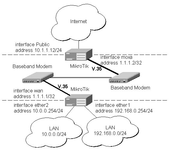
Synchronous Line ApplicationsTwo possible synchronous line configurations are discussed in the following examples: MikroTik Router to MikroTik RouterLet us consider the following network setup with two MikroTik Routers connected to a leased line with baseband modems:
The driver for MOXA C101 card should be loaded and the interface should be enabled according to the instructions given above. The IP addresses assigned to the synchronous interface should be as follows:
[MikroTik] ip address> add address 1.1.1.1/32 interface wan \
network 1.1.1.2 broadcast 255.255.255.255
[MikroTik] ip address> print
  # ADDRESS         NETMASK         NETWORK         BROADCAST       INTERFACE
  0 10.0.0.254      255.255.255.0   10.0.0.254      10.0.0.255      ether2
  1 192.168.0.254   255.255.255.0   192.168.0.254   192.168.0.255   ether1
  2 1.1.1.1         255.255.255.255 1.1.1.2         255.255.255.255 wan
[MikroTik] ip address> /ping 1.1.1.2
1.1.1.2 pong: ttl=255 time=27 ms
1.1.1.2 pong: ttl=255 time=27 ms
1.1.1.2 pong: ttl=255 time=27 ms
3 packets transmitted, 3 packets received, 0% packet loss
round-trip min/avg/max = 27/27.0/27 ms
[MikroTik] ip address>
Note, that for the point-to-point link the network mask is set to 32 bits, the argument 'network' is set to the IP address of the other end, and the broadcast address is set to 255.255.255.255. The default route should be set to the gateway router 1.1.1.2: [MikroTik] ip route> add gateway 1.1.1.2 interface wan [MikroTik] ip route> pr # DST-ADDRESS NETMASK GATEWAY PREF-ADDRESS INTE... 0 10.0.0.0 255.255.255.0 0.0.0.0 10.0.0.213 ether2 D K 1 192.168.0.0 255.255.255.0 0.0.0.0 192.168.0.254 ether1 D K 2 1.1.1.2 255.255.255.255 0.0.0.0 1.1.1.1 wan D K 3 0.0.0.0 0.0.0.0 1.1.1.2 0.0.0.0 wan [MikroTik] ip route> The configuration of the Mikrotik router at the other end is similar:
[MikroTik] ip address> add address 1.1.1.2/32 interface moxa \
network 1.1.1.1 broadcast 255.255.255.255
[MikroTik] ip address> print
  # ADDRESS         NETMASK         NETWORK         BROADCAST       INTERFACE
  0 10.1.1.12       255.255.255.0   10.1.1.12       10.1.1.255      Public
  1 1.1.1.2         255.255.255.255 1.1.1.1         255.255.255.255 moxa
[MikroTik] ip address> /ping 1.1.1.1
1.1.1.1 pong: ttl=255 time=27 ms
1.1.1.1 pong: ttl=255 time=27 ms
1.1.1.1 pong: ttl=255 time=27 ms
3 packets transmitted, 3 packets received, 0% packet loss
round-trip min/avg/max = 27/27.0/27 ms
[MikroTik] ip address>
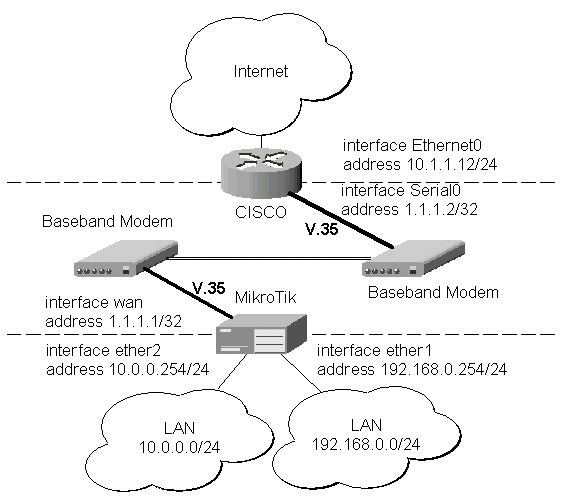
The driver for MOXA C101 card should be loaded and the interface should be enabled according to the instructions given above. The IP addresses assigned to the synchronous interface should be as follows:
[MikroTik] ip address> add address 1.1.1.1/32 interface wan \
network 1.1.1.2 broadcast 255.255.255.255
[MikroTik] ip address> print
  # ADDRESS         NETMASK         NETWORK         BROADCAST       INTERFACE
  0 10.0.0.254      255.255.255.0   10.0.0.254      10.0.0.255      ether2
  1 192.168.0.254   255.255.255.0   192.168.0.254   192.168.0.255   ether1
  2 1.1.1.1         255.255.255.255 1.1.1.2         255.255.255.255 wan
[MikroTik] ip address> /ping 1.1.1.2
1.1.1.2 pong: ttl=255 time=27 ms
1.1.1.2 pong: ttl=255 time=27 ms
1.1.1.2 pong: ttl=255 time=27 ms
3 packets transmitted, 3 packets received, 0% packet loss
round-trip min/avg/max = 27/27.0/27 ms
[MikroTik] ip address>
Note, that for the point-to-point link the network mask is set to 32 bits, the argument 'network' is set to the IP address of the other end, and the broadcast address is set to 255.255.255.255. The default route should be set to the gateway router 1.1.1.2: [MikroTik] ip route> add gateway 1.1.1.2 interface wan [MikroTik] ip route> pr # DST-ADDRESS NETMASK GATEWAY PREF-ADDRESS INTE... 0 10.0.0.0 255.255.255.0 0.0.0.0 10.0.0.213 ether2 D K 1 192.168.0.0 255.255.255.0 0.0.0.0 192.168.0.254 ether1 D K 2 1.1.1.2 255.255.255.255 0.0.0.0 1.1.1.1 wan D K 3 0.0.0.0 0.0.0.0 1.1.1.2 0.0.0.0 wan [MikroTik] ip route> The configuration of the CISCO router at the other end (part of the configuration) is:
CISCO#show running-config
Building configuration...

Current configuration:
...
!
interface Ethernet0
 description connected to EthernetLAN
 ip address 10.1.1.12 255.255.255.0
!
interface Serial0
 description connected to MikroTik
 ip address 1.1.1.2 255.255.255.252
 serial restart-delay 1
!
ip classless
ip route 0.0.0.0 0.0.0.0 10.1.1.254
!
...
end

CISCO#
Send ping packets to the MikroTik router:
CISCO#ping 1.1.1.1

Type escape sequence to abort.
Sending 5, 100-byte ICMP Echos to 1.1.1.1, timeout is 2 seconds:
!!!!!
Success rate is 100 percent (5/5), round-trip min/avg/max = 28/32/40 ms
CISCO#
|
Overview
PPTP (Point to Point Tunnel Protocol) supports encrypted tunnels over IP. The Mikrotik RouterOS implementation includes a PPTP client, a PPTP dynamic server, and a PPTP static server. The following tunnels are supported:
General usage of PPTP tunnels:
Topics covered in this section:
PPTP Installation on the MikroTik RouterOS v2.3
The pptp-2.3.0.npk(less than 160KB) package and the ppp-2.3.0.npk(less than 370KB) are required. The package can be downloaded from MikroTiks web page www.mikrotik.com . To install the packages, please upload them to the router with ftp and reboot. You may check to see if the PPTP and PPP packages are installed with the command:
[mikrotik]> system package print
  # NAME                                             VERSION    BUILD UNINSTALL
  0 routing                                          2.3.6      5     no
  1 aironet                                          2.3.6      5     no
  2 wavelan                                          2.3.6      5     no
  3 system                                           2.3.6      5     no
  4 snmp                                             2.3.6      5     no
  5 option                                           2.3.6      5     no
  6 ppp                                              2.3.6      5     no
  7 pptp                                             2.3.6      5     no
  8 pppoe                                            2.3.6      5     no
  9 radiolan                                         2.3.6      5     no
 10 ssh                                              2.3.6      5     no
[mikrotik]>
Lines six and seven show that the PPTP and PPP packages are installed.
Hardware resource usage
PPTP uses a minimum amount of memory. The current version of PPTP on RouterOS v2.3 uses a CPU intensive system which will run 5.6Mb/s on a Celeron 600MHz CPU. RouterOS v2.4 has a re-written PPTP engine that will run approximately 60Mb/s on a Celeron 600MHz CPU.
PPTP protocol description
Though the following may sound complex, our implementation of PPTP is easy to setup and manage. PPTP, together with PPP, is a secure tunnel for transporting IP traffic. PPTP encapsulates PPP in virtual lines that run over IP. PPTP incorporates PPP and MPPE (Microsoft point to point encryption) to make encrypted links. The purpose of this protocol is to make well-managed secure connections between 1) routers and routers 2) routers and Windows clients (or other OS with PPTP support). PPTP includes PPP authentication and accounting for each PPTP connection. Full authentication and accounting of each connection may be done through a RADIUS client or locally. There are also additional PPP configurations for management of users and connections. MPPE 40bit RC4 and MPPE 128bit RC4 encryption are supported. PPTP traffic uses TCP port 1723 and IP protocol ID 47, as assigned by the Internet Assigned Numbers Authority (IANA). PPTP can be used with most firewalls and routers by enabling traffic destined for port 1723 to be routed through the firewall or router. PPTP connections cannot be setup though a masqueraded/NAT IP connection. Please see the Microsoft and RFC links at the end of this section for more information.
PPTP client setup
Each PPTP connection is composed of a server and a client. The MikroTik RouterOS may function as a server or client or for various configurations, it may be the server for some connections and client for other connections. For example, the client created below could connect to a Windows 2000 server, another MikroTik Router, or another router which supports a PPTP server. To add a PPTP client to the router:
[Rack1u] interface pptp-client> add name rack2u pap no chap no ms-chapv2 yes encryption required user testDescriptions of settings:
connect-to 10.5.8.171 idle-timeout 0 session-timeout 0
[Rack1u] interface pptp-client> print
(0) name: rack2u mtu: 1460 mru: 1460 pap: no chap: no ms-chapv2: yes
encryption: required user: test connect-to: 10.5.8.171 idle-timeout: 0
session-timeout: 0
nameFor a reference.
Pap, chap, ms-chapv2Encrypted links are only supported when ms-chapv2 is selected. This is a feature of the protocol. It is suggested that pap and chap always be set to no, unless there is a special situation which requires an unencrypted link.
encryption
Will only work in encrypted mode when ms-chapv2 authentication is used. For most links, it should be set to required.
none no encryption
optional 40bit or 128bit if server requests this
required 40bit or 128bit if server agrees, link will be shut down if no agreement
non-stateless (description) key is changed approximately every hour or depending on traffic
stateless same as required plus key is changed for every packet
user
A user name and password must be added to the client routers user database. The user must be added with the attribute of group PPP. When the client is being authenticated by the server, the client will send this user and the password from the client routers user database. The server user database must have the same user and password and PPP group attribute to authenticate the link.
Connect-toThe IP address of the PPTP server.
idle-timeout
The link will be terminated if there is no activity with-in the time set in seconds. When set to 0, there is no timeout.
session-timeout
The maximum time the connection can stay up. When set to 0, there is no timeout.
client-address
IP address of client connecting to the PPTP static server
PPTP dynamic server setup
The router supports one PPTP dynamic server. This server supports unlimited connections from clients. For each current connection, a dynamic interface is created. While the PPTP dynamic server supports multiple clients, it does not support static routes, filters, and other IP level features that need to be attached to static interfaces. The PPTP static server supports routes and other IP level features.
To add a dynamic server:
[Rack2u] interface pptp-dynamic-server server> set enabled yes pap no chap no ms-chapv2 yes encryption required
local-address-from 10.9.0.1 local-address-to 10.9.0.1 remote-address-from 10.9.0.1 remote-address-to 10.9.0.100
[Rack2u] interface pptp-dynamic-server server> print
enabled: yesDescriptions of settings:
pap: no
chap: no
ms-chapv2: yes
encryption: required
mtu: 1460
mru: 1460
idle-timeout: 0
session-timeout: 0
local-address-from: 10.9.0.1
local-address-to: 10.9.0.1
remote-address-from: 10.9.0.2
remote-address-to: 10.9.0.100
enabled
Yes or No
Pap, chap, ms-chapv2Encrypted links are only supported when ms-chapv2 is selected. This is a feature of the protocol. It is suggest that pap and chap always be set to no, unless there is a special situation which requires an unencrypted link.
encryption
Will only work in encrypted mode when ms-chapv2 authentication is used. For most links, it should be set to required.
none no encryption
optional 40bit or 128bit if client agrees to this
required 40bit or 128bit if client agrees, link will be shut down if no agreement
non-stateless (description) key is changed approximately every hour or depending on traffic
stateless same as required plus key is changed for every packet
mtu
The default mtu is set to 1460 because of the PPTP overhead. It may be changed for special situations.
mru
The default mru is set to 1460 because of the PPTP overhead. It may be changed for special situations.
idle-timeout
The link will be terminated if there is no activity with-in the time set in seconds. When set to 0, there is no timeout.
session-timeout
The maximum time the connection can stay up. When set to 0, there is no timeout.
local-address-from and local-address-to
The IP address of the PPTP local server. Both the -from and to can be the same. The same local server address will be used on all connections that are created.
remote-address-from and remote-address-to
This should be set to an IP range. This may limit the number of current connections if there are no free IPs available when a new connection is initiated.
PPTP static server setup
The PPTP static server is made for permanent connections between two routers. One side of the PPTP tunnel must be set up as a static server and the other side as a client. On both the static server side and the client side, it will be possible to add static routes, filters, and any other IP level features for example an EoIP tunnel may be put on top of the PPTP encrypted tunnel to make an encrypted LAN-to-LAN bridge.
To add a PPTP static server interface:
[Rack2u] interface pptp-static-server> add name rack1u client-address 10.5.8.169 pap no chap no ms-chapv2 yesDescriptions of settings:
encryption required local-address 10.7.0.1 remote-address 10.7.0.2
[Rack2u] interface pptp-static-server> print
(0) name: rack1u client-address: 10.5.8.169 pap: no chap: no ms-chapv2: yes encryption: required
mtu: 1460 mru: 1460 idle-timeout: 0 session-timeout: 0 local-address: 10.7.0.1 remote-address: 10.7.0.2
Pap, chap, ms-chapv2
Encrypted links are only supported when ms-chapv2 is selected. This is a feature of the protocol. It is suggest that pap and chap always be set to no, unless there is a special situation which requires an unencrypted link.
encryption
Will only work in encrypted mode when ms-chapv2 authentication is used. For most links, it should be set to required.
none no encryption
optional 40bit or 128bit if client agrees to this
required 40bit or 128bit if client agrees, link will be shut down if no agreement
non-stateless (description) key is changed approximately every hour or depending on traffic
stateless same as required plus key is changed for every packet
mtu
The default mtu is set to 1460 because of the PPTP overhead. It may be changed for special situations.
mru
The default mru is set to 1460 because of the PPTP overhead. It may be changed for special situations.
idle-timeout
A standard PPP setting. The link will be terminated if there is no activity with-in the time set in seconds. When set to 0, there is no timeout.
session-timeout
The maximum time the connection can stay up. When set to 0, there is no timeout.
local-address
The IP address of the PPTP local server. The same local server address can be used on multiple static sever interfaces.
remote-address
This should be set to an IP address of the remote client. PPTP connections for this static server will only be accepted from this address.
PPTP monitoring
To monitor a PPTP client:
[Rack1u] interface pptp-client> mon 0Descriptions of display:
uptime: 2s
encoding: MPPE 128 bit, stateless
status: Connected
uptime


Connection time displayed in days, hours, minutes, and seconds.
encoding
Encryption being used in this connection.
statusThe status of this client may be:
Dialing attempting to make a connection
Connected self-explanatory
Terminated interface is not enabled or the other side will not establish a connection
PPTP router-to-router secure tunnel example
The following is an example of connecting two Intranets using an encrypted PPTP tunnel over the Internet.

There are three routers in this example:
HomeOffice
Interface LocalHomeOffice 10.150.2.254/24
Interface ToInternet 192.168.80.1/24
Internet
Interface ToHomeOffice 192.168.80.254/24
Interface ToRemoteOffice 192.168.81.254/24
RemoteOffice
Interface ToInternet 192.168.81.1/24To add a secure Tunnel between the HomeOffice and RemoteOffice local Intranet, add an identical user and password with the group ppp to both the HomeOffice and RemoteOffice router.
Interface LocalRemoteOffice 10.150.1.254/24
[RemoteOffice] user> add name remote password remote group pppAdd a PPTP static server interface to the HomeOffice router -
[HomeOffice] user> add name remote password remote group ppp
[HomeOffice] interface pptp-static-server> print
0   name: FromRemoteOffice client-address: 192.168.81.1 pap: no chap: no
    ms-chapv2: yes encryption: required mtu: 1460 mru: 1460 idle-timeout: 0
    session-timeout: 0 local-address: 10.0.103.1 remote-address: 10.0.103.2
Add a PPTP client to the RemoteOffice router
[RemoteOffice] interface pptp-client> pr
0   name: Tunnel_To_HomeOffice mtu: 1460 mru: 1460 pap: no chap: no
    ms-chapv2: yes encryption: required user: remote connect-to: 192.168.80.1
    idle-timeout: 0 session-timeout: 0
To route the local Intranets over the PPTP tunnel add these routes
To the HomeOffice router
  # DST-ADDRESS     NETMASK         GATEWAY         PREF-ADDRESS    INTE...
  4 10.150.2.0      255.255.255.0   10.0.103.1      0.0.0.0         Tunn...
To the RemoteOffice router
  # DST-ADDRESS     NETMASK         GATEWAY         PREF-ADDRESS    INTE...
  7 10.150.1.0      255.255.255.0   10.0.103.2      0.0.0.0         From...

Test the PPTP tunnel connection
[RemoteOffice]> /ping 10.0.103.1
10.0.103.1 pong: ttl=255 time=3 ms
10.0.103.1 pong: ttl=255 time=3 ms
10.0.103.1 pong: ttl=255 time=3 ms
ping interrupted
3 packets transmitted, 3 packets received, 0% packet loss
round-trip min/avg/max = 3/3.0/3 ms
Test the connection through the PPTP tunnel to the Intranet interface
[RemoteOffice]> /ping 10.150.2.254To bridge a LAN over this secure tunnel, please the EoIP section of the manual. To set the maximum speed for traffic over this tunnel, please the Queues section.
10.150.2.254 pong: ttl=255 time=3 ms
10.150.2.254 pong: ttl=255 time=3 ms
10.150.2.254 pong: ttl=255 time=3 ms
ping interrupted
3 packets transmitted, 3 packets received, 0% packet loss
round-trip min/avg/max = 3/3.0/3 ms
PPTP Windows setup
Microsoft provides PPTP client support for Windows NT, 2000, ME, 98se, and 98. Windows 98se, 2000, and ME include support in the Windows setup or automatically install PPTP. For 95, NT, and 98, installation requires a download from Microsoft. Many ISPs have made help pages to assist clients with Windows PPTP installation. A zipped download of an instructional web page is available in PPTP_client_files.zip this can be found in the utilities section of the download section. This zipped file also includes files needed from Microsoft for upgrading Windows 95 and 98 to support PPTP.
Links:
http://www.real-time.com/Customer_Support/PPTP_Config/pptp_config.html
http://www.microsoft.com/windows95/downloads/contents/WUAdminTools/S_WUNetworkingTools/W95WinsockUpgrade/Default.asp
Sample instructions for PPTP (VPN) installation and client setup Windows 98se:
If the VPN (PPTP) support is installed, select Dial-up networking and create a new connection. The option to create a VPN should be selected. If there is no VPN options, then follow the installation instructions below. When asked for the Host name or IP address of the VPN server, type the IP address of the router. Double-click on the new icon and type the correct user name and password (must also be in the user database on the router or RADIUS server used for authentication). The setup of the connections takes nine seconds after selection the connect button. It is suggested that the connection properties be edited so that NetBEUI, IPX/SPX compatible, and Log on to network, are unselected. The setup time for the connection will then be two seconds after the connect button is selected.Links for PPTP documentation:
http://msdn.microsoft.com/library/backgrnd/html/understanding_pptp.htm
http://support.microsoft.com/support/kb/articles/q162/8/47.asp
http://www.ietf.org/rfc/rfc2637.txt?number=2637
http://www.ietf.org/rfc/rfc3078.txt?number=3078
http://www.ietf.org/rfc/rfc3079.txt?number=3079
Document revision 3-August-2001
This document applies to MikroTik RouterOS V2.4
Overview
The PPPoE (Point to Point Protocol over Ethernet) protocol provides extensive user management, network management, and accounting benefits to ISPs and network administrators. Currently, PPPoE is used mainly by ISPs to control client connections for xDSL and cable modems. PPPoE is an extension of the standard dial-up and synchronous protocol PPP. The transport is over Ethernet as opposed to modem transport. A PPPoE connection is composed of a client and an access concentrator (server). The client may be a Windows computer that has the PPPoE client protocol installed. The MikroTik RouterOS supports both the client and access concentrator implementations of PPPoE. The PPPoE client and server work over any Ethernet level interface on the router wireless 802.11 (Aironet, Cisco, WaveLAN), 10/100/1000 Mb/s Ethernet, RadioLAN, and EoIP (Ethernet over IP tunnel). No encryption, MPPE 40bit RSA, and MPPE 128bit RSA encryption are supported. Our RouterOS has a RADIUS client that can be used for authentication of all PPP type connections including PPPoE. For more information on PPP authentication, see the PPP Authentication and Accounting section of the manual.
Supported connections:
· MikroTik RouterOS PPPoE client to any PPPoE server (access concentrator)
· MikroTik RouterOS server (access concentrator) to multiple PPPoE clients (clients are available for all OSs and some routers)
Topics covered in this manual:
· Installation
· Hardware resource usage
· PPPoE client setup
· PPPoE server setup (access concentrator)
· PPPoE bandwidth settings
· PPPoE in a multipoint wireless 802.11b network
The pppoe-2.4.0.npk(less than 160KB) package and the ppp-2.4.0.npk(less than 370KB) are required. The package can be downloaded from MikroTiks web page www.mikrotik.com . To install the packages, please upload them to the router with ftp and reboot. You may check to see if the packages are installed with the command:
[mikrotik]> system package print
  # NAME                                             VERSION    BUILD UNINSTALL
  0 routing                                          2.4.0      1     no
  1 aironet                                          2.4.0      1     no
  2 wavelan                                          2.4.0      1     no
  3 system                                           2.4.0      1     no
  4 snmp                                             2.4.0      1     no
  5 option                                           2.4.0      1     no
  6 ppp                                              2.4.0      1     no
  7 pptp                                             2.4.0      1     no
  8 pppoe                                            2.4.0      1     no
  9 radiolan                                         2.4.0      1     no
 10 ssh                                              2.4.0      1     no

[mikrotik]>
Lines six and eight show that the PPP and PPPoE packages are installed.
The PPPoE client supports high-speed connections. It is fully compatible with the MikroTik PPPoE server (access concentrator). Test with different ISPs and access concentrators are currently underway.
Some connection instructions may use the form where the phone number is MikroTik_AC\mt1 to indicate that MikroTik_AC is the access concentrator name and mt1 is the service name.
[RemoteOffice] interface pppoe-client> print0 name=pppoe-out1 interface=gig service-name=testSN user=john pap=no chap=yes ms-chapv2=no mtu=1492 mru=1492 idle-timeout=0s session-timeout=0s add-default-route=yes dial-on-demand=no use-peer-dns=no encryption=none compression=no local-address=0.0.0.0 remote-address=0.0.0.0 ac-name="" mss-update=1452Descriptions of settings:
nameThis settable name will appear in interface and IP address list when the PPPoE session is active.
interfaceThe PPPoe client can be attached to any Ethernet like interface for example: wireless, 10/100/1000 Ethernet, and EoIP tunnels.
mtu and mruRepresents the MTU and MRU when the 8 byte PPPoE overhead is subtracted from the standard 1500 byte Ethernet packet
Pap, chap, ms-chapv2It is suggested that chap be set to yes to have encrypted authentication. If there is a special situation that requires an encrypted link, only ms-chapv2 should be set to yes. Encrypted links are only supported when ms-chapv2 is selected. This is a requirement of the protocol.
encryptionWill only work in encrypted mode when ms-chapv2 authentication is used. For most links, it should be set to none.
none no encryption
optional 40bit or 128bit if server requests this
required 40bit or 128bit if server agrees, link will be shut down if no agreement
non-stateless (description) key is changed approximately every hour or depending on traffic
stateless same as required plus key is changed for every packet
user
A user name and password must be added to the client routers user database. The user must be added with the attribute of group PPP. When the server is authenticating the client, the client will send this user and the password from the client routers user database. The server user database must have the same user and password and PPP group attribute to authenticate the link unless the RADIUS client is enabled.
idle-timeoutThe link will be terminated if there is no activity with-in the time set in seconds. When set to 0, there is no timeout.
session-timeoutThe maximum time the connection can stay up. When set to 0, there is no timeout.
dial-on-demandConnects to AC only when outbound traffic is generated. The client will not stay permanently connected.
use-peer-dnsSets the router default DNS to the PPP peer DNS.
compressionMay be selected if encryption is not used. The default setting of no compression is suggested.
local-addressIf the ppp server allows, a local-address may be set. The default setting of 0.0.0.0 is suggested. In this case, the address set by the server will be used.
session-timeoutThe maximum time the connection can stay up set in seconds. When set to 0, there is no timeout.
remote-addressIf the ppp server allows, a remote-address may be set. The default setting of 0.0.0.0 is suggested.
serviceThe service name set on the access concentrator. Many ISPs give user-name and address in the form of user-name@service-name
ac-nameThis may be left blank and the client will connect to any access concentrator that offers the service name selected.
Add-default-routeSelect yes to have a default route added automatically.
mss-updateThis setting changes the mss (maximum segment size) setting of each packet to the selected size. The default of 1452 is suggested. This fixes a common problem for PPPoE when mis-configured servers or networks do not let the IP protocol work properly. The common symptom is a partial download of a web page.
PPPoE server setup (access concentrator)
The PPPoE server (access concentrator) supports multiple servers for each interface with differing service names. Currently, a maximum of 5000 PPPoE connections are supported. Currently the throughput of the PPPoE server has been tested to 160Mb/s on a Celeron 600 CPU. Using higher speed CPUs should increase the throughput proportionately.
The setting below is the optimal setting to work with Windows clients such as RASPPPoE client for Win98/2000/ME. The password authentication and encryption are set to pap no chap yes ms-chapv2 no encryption none specifically to ensure a quick login by the windows client. In the example below, the login is encrypted with PAP. Currently it is possible to make encrypted links to Windows clients, but usually they quit passing IP after five minutes but remain connected and do show that data is passed this is a bug which is being worked on. There are no problems with encryption between MikroTik PPPoE client and server.
The access concentrator has a hard limit of 5000 current connections. The user setting for the connections limit is done by setting the remote-to and remote-from IP addresses range. For example, For a limit of 1020 users: remote-from=10.0.0.1 remote-to=10.0.4.255 . Even if you are using a RADIUS server for client addresses, the remote-from and remote-to arguments must include an IP range which will limit/enable the number of current connections.
The access concentrator name and PPPoE service name are used by clients to identify the access concentrator to register with. The access concentrator name name is the same as the identity of the router. The identity many be set with the command: /system identity set xxxxx .
  0   service-name=testSN interface=gig local-from=5.5.5.1 local-to=5.5.5.1

      remote-from=6.6.6.1 remote-to=6.6.6.250 mtu=1492 mru=1492 pap=no chap=yes

      ms-chapv2=no idle-timeout=0s session-timeout=0s compression=no

      encryption=none
Descriptions of settings:
Pap, chap, ms-chapv2It is suggest that chap always be set to yes. PAP is best disabled because it sends the user-name and password in clear text. ms-chapv2 should be disable as it is not needed unless there is a special situation that requires an encrypted link. Encrypted links are only supported when ms-chapv2 is selected. This is a feature of the protocol.
encryption
Will only work in encrypted mode when ms-chapv2 authentication is used. For most setups, it should be set to none.
none no encryption
optional 40bit or 128bit if client agrees to this
required 40bit or 128bit if client agrees, link will be shut down if no agreement
non-stateless (description) key is changed approximately every hour or depending on traffic
stateless same as required (non-stateless) plus key is changed for every packet
interface
The PPPoe server can be attached to any Ethernet like interface for example: wireless, 10/100/1000 Ethernet, and EoIP tunnels.
compressionStandard PPP level compression.
serviceThe PPPoE service name.
mtuThe default mtu is set to 1492 because of the PPPoE overhead. It may be changed for special situations.
mruThe default mru is set to 1492 because of the PPPoE overhead. It may be changed for special situations.
idle-timeoutA standard PPP setting. The link will be terminated if there is no activity with-in the time set in seconds. When set to 0, there is no timeout.
session-timeoutThe maximum time the connection can stay up in the format of Xh or Xm or Xs. When set to 0, there is no timeout.
local-address-from and local-address-toThe IP address pool of the PPPoE local server for each new PPPoE connection. One local address can be used on multiple static sever interfaces. Usually, it is best that this is not a real IP address. Only the client could have a use for a real IP address. Example: local-address-from 10.0.0.1 local-address-to 10.0.0.1 .
remote-address-from and remote-address-toThe IP address pool for the PPPoE remote client for each new PPPoE connection. One address must be available for each current connection the number in the range selected will be the maximum number of current connections. If radius authentication is used to give addresses, it is still required to have a range of addresses set in this server setup.
Links for PPPoE documentation:
http://www.ietf.org/rfc/rfc2516.txt
http://www.nts.com/products/enternet_overvw.html
http://www.carricksolutions.com/
http://www.cisco.com/warp/public/cc/pd/as/6400/prodlit/6400_ds.htm
© Copyright 2001, MikroTik
Overview
The IPIP tunneling implementation on the MikroTik RouterOS is RFC 2003 compliant. IPIP tunnel is a simple protocol that encapsulates IP packets in IP to make a tunnel between two routers. The IPIP interface appears as an interface. Many routers, including Cisco and Linux based, support this protocol. This protocol makes multiple network schemes possible.
Network setups with IPIP interfaces:
Topics covered in this section:
IPIP installation on the MikroTik RouterOS v2.3
The IPIP tunnel feature is included in the system package.
Hardware resource usage
This protocol uses a minimum of resources.
IPIP interface and protocol description
An IPIP interface should be configured on two routers that have the possibility for an IP level connection and are RFC 2003 compliant. The IPIP tunnel may run over any connection that transports IP. Each IPIP tunnel interface can connect with one remote router which has a corresponding interface configured. An unlimited number of IPIP tunnels may be added to the router. For more details on IPIP tunnels, see RFC 2003.
IPIP setup
To add an IPIP interface:
[Rack1u] interface ipip> add name test_IPIP mtu 1480 local-address 10.5.8.169 remote-address 10.5.8.171Descriptions of settings:
[Rack1u] interface ipip> print
(0) name: test_IPIP mtu: 1480 local-address: 10.5.8.169
remote-address: 10.5.8.171
nameInterface name for reference
mtuShould be set to 1480 bytes to avoid fragmentation of packets. May be set to 1500bytes if mtu path discovery is not working properly on links.
local-addressLocal address on router which send IPIP traffic to the remote side.
remote-address
The IP address of the other side of the IPIP tunnel may be any RFC 2003 compliant router.
There is no authentication or state for this interface. The bandwidth usage of the interface may be monitored with the monitor feature from the interface menu.
IPIP Cisco example
Our IPIP implementation has been tested with Cisco 1005. Sample of the Cisco 1005 configuration:
interface Tunnel0
 ip address 10.3.0.1 255.255.255.0
tunnel source 10.5.8.179
tunnel destination 10.5.8.169
tunnel mode ipip
Additional Resources
Links for IPIP documentation:
http://www.ietf.org/rfc/rfc1853.txt?number=1853
http://www.ietf.org/rfc/rfc2003.txt?number=2003
http://www.ietf.org/rfc/rfc1241.txt?number=1241
Overview
Ethernet over IP (EoIP) Tunneling is a RouterOS protocol that creates an Ethernet tunnel between two routers on top of an IP connection. The EoIP interface appears as an Ethernet interface. When the bridging function of the router is enabled, all Ethernet level traffic (all Ethernet protocols) will be bridged just as if there where a physical Ethernet interface and cable between the two routers (with bridging enabled). This protocol makes multiple network schemes possible.
Network setups with EoIP interfaces:
Topics covered in this section:
EoIP installation on the MikroTik RouterOS v2.3
The Ethernet over IP tunnel feature is included in the system package.
Hardware resource usage
To achieve 100Mb/s Ethernet level wire speed (85Mb/s), it is suggested that Celeron 600MHz and higher CPUs be used on each router in this situation, the CPU usage was ~60%. Optimization of this implementation will soon decrease the usage of resource usage.
EoIP interface and protocol description
An EoIP interface should be configured on two routers that have the possibility for an IP level connection. The EoIP tunnel may run over an IPIP tunnel, a PPTP 128bit encrypted tunnel, a PPPoE connection, or any connection that transports IP. Each EoIP tunnel interface can connect with one remote router which has a corresponding interface configured with the same Tunnel ID. Up to sixteen (numbered 0-15) EoIP tunnels may be created on a router (please contact us if there is an important reason to increase the number of EoIP tunnels per router). The EoIP interface appears as an Ethernet interface under the interface list. This interface supports all features of and Ethernet interface. IP addresses and other tunnels may be run over the interface. The EoIP protocol encapsulates Ethernet frames in UDP packets and sends them to the remote side of the EoIP tunnel. The tunnel transmits and listens to the UDP port 4444 + tunnel ID.
EoIP setup
To add an EoIP interface:
[Rack1u] interface eoip> add name to_2u tunnel-id 1 remote-address 10.5.8.171
0 name: to_2u mtu: 1500
mac-address: FE:FD:00:00:00:00 arp: enabled
tunnel-id: 1 remote-address: 10.111.0.1
Descriptions of settings:
name
Interface name for reference
mtu
Should be set to 1500bytes.
mac-address
A default virtual MAC address is generated. It may be changed if there is a conflict.
arp
Enabled by default.
tunnel-id
Should be a number from 0-16 which has not been used for another EoIP tunnel.
remote-address
The IP address of the other side of the EoIP tunnel must be a MikroTik router.
To make an Ethernet bridge between two routers with EoIP tunnels, bridging should be enabled on both routers. There is no authentication or state for this interface. The bandwidth usage of the interface may be monitored with the monitor feature from the interface menu.
Managing ISDN Server from Console
It is done from "interface isdn-server" submenu.
| Command Syntax | Description |
|---|---|
|
|
Print ISDN Server information |
|
set <number> [name <interface name>] [enable] [disable] [mtu <MTU>] [mru <MRU>] |
Configure ISDN Server |
|
remove <number> |
Remove ISDN Server |
|
find |
Find |
|
export |
Export ISDN Server settings |
| monitor <interface> | Monitor ISDN server in real time |
Where <interface> is an interface name or number obtained from "print" command.
Managing ISDN Client from JAVA
It is done from Interfaces list. To add isdn client you have to choose add
![]() and then ISDN client.
If you want to change isdn client settings you have to double click on added
isdn client interface in Interace list.
and then ISDN client.
If you want to change isdn client settings you have to double click on added
isdn client interface in Interace list.
Managing ISDN Client from Console
It is done from "interface isdn-client" submenu.
| Command Syntax | Description |
|---|---|
|
|
Print ISDN Client information |
|
set <number> [name <interface name>] [enable] [disable] [mtu <MTU>] [mru <MRU>] |
Configure ISDN Client |
|
remove <number> |
Remove ISDN Client |
|
find |
Find |
|
export |
Export ISDN Client settings |
| monitor <interface> | Monitor ISDN Client in real time |
Where <interface> is an interface name or number obtained from "print" command.
Managing LMC- WAN from Console
It is done from "lmc-wan" submenu.
| Command Syntax | Description |
|---|---|
|
|
Print LMC-WAN information |
|
set <number> [name <interface name>] [enable] [disable] [mtu <MTU>] |
Configure LMC-WAN |
|
find |
Find |
|
export |
Export LMC-WAN settings |
| monitor <interface> | Monitor LMC-WAN in real time |
Where <interface> is an interface name or number obtained from "print" command.
For more information about the CISCO/Aironet PCI/ISA adapter hardware please see the relevant
Users Guides and Technical Reference Manuals in .pdf format:
Documentation about CISCO/Aironet Wireless Bridges and Access Points can be found in archives:
Contents of the Manual
The following topics are covered in this manual:
[mikrotik]> system package print
  # NAME                                                VERSION    BUILD UNINSTALL
  0 system                                              2.3.7      8     no
  1 ppp                                                 2.3.7      6     no
  2 pppoe                                               2.3.7      10    no
  3 pptp                                                2.3.7      6     no
  4 routing                                             2.3.7      7     no
  5 ssh                                                 2.3.6      7     no
  6 aironet                                             2.3.7      6     no
[mikrotik]>
[mikrotik]> system resource irq print
IRQ OWNER
1   keyboard                                                                  U
2   APIC                                                                      U
3   Local                                                                     U
4   serial port                                                               U
5
6
7
8
9
10
11  Public                                                                    U
12
13  FPU                                                                       U
14  IDE 1                                                                     U
[mikrotik]> system resource io print
IO        OWNER
0020-003f APIC
0040-005f timer
0060-006f keyboard
0080-008f DMA
00a0-00bf APIC
00c0-00df DMA
00f0-00ff FPU
01f0-01f7 IDE 1
0300-031f Local
03c0-03df VGA
03f6-03f6 IDE 1
03f8-03ff serial port
6100-61ff Public
f000-f007 IDE 1
f008-f00f IDE 2
Installing the Wireless Adapter
The basic installation steps of the wireless adapter should be as follows:
Loading the Driver for the Wireless Adapter
PCI and PC (PCMCIA) cards do not require a 'manual' driver loading, since they
are recognized automatically by the system and the driver is loaded at the system startup.
The ISA card requires the driver to be loaded by issuing the following command:
[mikrotik]> driver load pc-isa io 0x180
[mikrotik]> driver print
  # DRIVER                                       IRQ IO     MEMORY     ISD...
  0 RealTek RTL8129/8139                                                      D
  1 ISA NE2000                                       0x300
  2 Aironet ISAxx00                                  0x180
[mikrotik] driver>
There can be several reasons for a failure to load the driver:
[mikrotik] interface> print
  # NAME                                                    TYPE        MTU
  0 Public                                                  ether       1500
  1 Local                                                   ether       1500
 (2)pc0                                                     pc          1500
[mikrotik] interface> set 2 name aironet
[mikrotik] interface> enable aironet
[mikrotik] interface> print
  # NAME                                                    TYPE        MTU
  0 Public                                                  ether       1500
  1 Local                                                   ether       1500
  2 aironet                                                 pc          1500
More configuration and statistics parameters can be found under the '/interface pc' menu:
[mikrotik] interface> pc
[mikrotik] interface pc> print
0   name: aironet mtu: 1500 mac-address: 00:40:96:29:02:88
    mode: infrastructure rts-threshold: 2312 fragmentation-threshold: 2312
    tx-power: 100 rx-diversity: right tx-diversity: right long-retry-limit: 16
    short-retry-limit: 16 channel: 2437MHz data-rate: auto
    ap1: 00:00:00:00:00:00 ap2: 00:00:00:00:00:00 ap3: 00:00:00:00:00:00
    ap4: 00:00:00:00:00:00 ssid1: tsunami ssid2: "" ssid3: "" modulation: cck
    client-name: "" beacon-period: 100 join-net: 10s arp: enabled
    firmware-version: PC4800A(3.65)

[mikrotik] interface pc>
Argument description:
number - Interface number in the list
name - Interface name
mtu - Maximum Transmit Unit
mode - Operation mode of the card (infrastructure / ad-hoc)
rts-threshold - RTS threshold
fragmentation-threshold - Fragmentation threshold
tx-power - Transmit power in mW
rx-diversity - Receive diversity (both / default / left / right)
tx-diversity - Transmit diversity (both / default / left / right)
long-retry-limit - Long retry limit
short-retry-limit - Short retry limit
channel - Channel frequency (2412MHz / 2422MHz / ... / 2484MHz)
data-rate - Data rate (11Mbit/s / 1Mbit/s / 2Mbit/s / 5.5Mbit/s / auto)
ap1 - Access Point 1
ap2 - Access Point 2
ap3 - Access Point 3
ap4 - Access Point 4
ssid1 - Service Set Identifier 1
ssid2 - Service Set Identifier 2
ssid3 - Service Set Identifier 3
modulation - Modulation mode (cck / default / mbok)
client-name - Client name
join-net - Beaconing period
arp - Address Resolution Protocol (disabled / enabled / proxy-arp)
You can monitor the status of the wireless interface:
[mikrotik] interface pc> monitor 0
quality: 0
strength: 0
current-rate: 11Mbit/s
current-frequency: 2437MHz
synchronized: no
associated: no
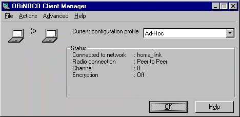
ssid: tsunami
access-point: FF:FF:FF:FF:FF:FF
access-point-name:
[mikrotik] interface pc>
If the wireless interface card is not registered to an AP, the green status led is blinking fast.
To set the wireless interface for working with an IEEE 802.11b access point (register to the AP), you should set the following parameters:
[mikrotik] interface pc> set 0 ssid1 mt
[mikrotik] interface pc> monitor 0
              quality: 63
             strength: 131
         current-rate: 11Mbit/s
    current-frequency: 2412MHz
         synchronized: yes
           associated: yes
                 ssid: mt
         access-point: 00:40:96:00:06:72
    access-point-name: Gulf
[mikrotik] interface pc>
If the wireless interface card is registered to an AP, the green status led is blinking slow.
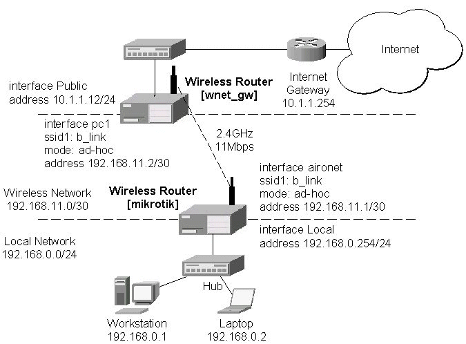
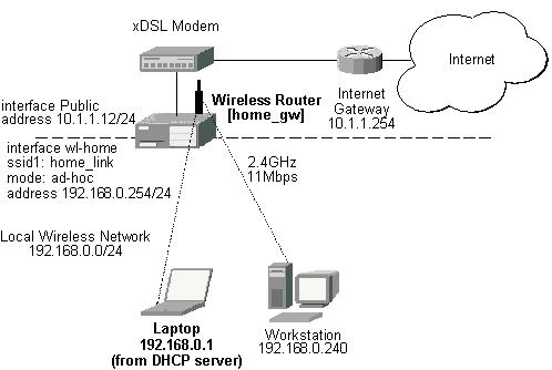
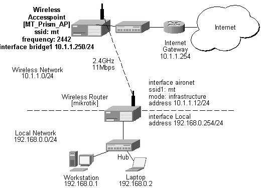
Two possible wireless network configurations are discussed in the following examples:
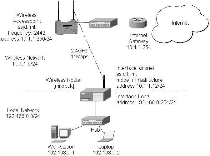
The access point is connected to the wired network's HUB and has IP address from the network 10.1.1.0/24. The minimum configuration required for the AP is:
Reminder! Please note, that the AP is not a router! It has just one network address, and is just like any host on the network. It resembles a wireless-to-Ethernet HUB or bridge. The AP does not route the IP traffic!
The minimum configuration for the MikroTik router's CISCO/Aironet wireless interface is:
[mikrotik] interface pc> set 0 ssid1 mt mode infrastructure
[mikrotik] interface pc> monitor 0
              quality: 62
             strength: 129
         current-rate: 11Mbit/s
    current-frequency: 2442MHz
         synchronized: yes
           associated: yes
                 ssid: mt
         access-point: 00:40:96:00:06:72
    access-point-name: Gulf
[mikrotik] interface pc>
The channel frequency argument does not have any meaning, since the frequency of the AP is used. The IP addresses assigned to the wireless interface should be from the network 10.1.1.0/24, e.g.:
[mikrotik] ip address> add address 10.1.1.12/24 interface aironet
[mikrotik] ip address> print
  # ADDRESS         NETMASK         NETWORK         BROADCAST       INTERFACE
  0 192.168.0.254   255.255.255.0   192.168.0.254   192.168.0.255   Local
  1 10.1.1.12       255.255.255.0   10.1.1.12       10.1.1.255      aironet
[mikrotik] ip address>
The default route should be set to the gateway router 10.1.1.254 (not the AP 10.1.1.250 !):
[mikrotik] ip route> add gw 10.1.1.254 interface aironet
[mikrotik] ip route> print
  # DST-ADDRESS     NETMASK         GATEWAY         PREF-ADDRESS    INTE...
  0 192.168.0.0     255.255.255.0   0.0.0.0         192.168.0.254   Local   D K
  1 10.1.1.0        255.255.255.0   0.0.0.0         10.1.1.12       aironet D K
  2 0.0.0.0         0.0.0.0         10.1.1.254      0.0.0.0         aironet
[mikrotik] ip route>
Arlan IC2200 interfaces include Aironets Arlan IC2200 (655) 2.4GHz 2Mbps ISA Client Cards. This hardware line has been discontinued.
Managing Arlan IC2200 Interfaces from Java
Arlan IC2200 specific parameters can be controlled from the Radio tab in interface details window. Current status (registration status and registered router and backbone) can be monitored in real time on Status tab in interface details window.
Managing Arlan IC2200 Interfaces from Console
Arlan IC2200 interface management is done in the submenu interface arlan.
| Command syntax | Description |
|---|---|
|
print [<interface>] |
Show interface(s) information |
|
set <interface> [enable] [disable]
|
Change interface properties |
|
monitor <interface> |
Monitor interface status in real time |
|
find |
|
|
export |
Where <interface> is interface name or number obtained from print command.
Interface status includes registration status and registered router and backbone.
Arlan IC2200 Parameter Description
| Name in Console | Name in Java | Description |
|---|---|---|
|
frequency |
Frequency |
Channel frequency in MHz. |
|
bitrate |
Bitrate |
Data Transmission speed in Mbits |
|
card-name |
Card Name |
Name of the client to be shown in the registration table of the Access Point or Bridge. Maximum 15 characters. |
|
sid |
SID |
Value of System Identifier. Should be the same for all nodes on the radio network. Maximum 31 character. |
|
mac-address |
MAC Address |
Medium Access Control Address |
|
tma-mode |
TMA mode |
Enable/Disable registration mode when client has to register to an AP2000 Access Point or BR2000-E Bridge. |
|
arp |
ARP |
Address Resolution Protocol settings |
For more information about the RadioLAN adapter hardware please see the relevant Users Guides and Technical Reference Manuals.
Contents of the Manual
The following topics are covered in this manual:
[MikroTik]> system package print
  # NAME                                             VERSION    BUILD UNINSTALL
  0 routing                                          2.3.15     21    no
  1 snmp                                             2.3.15     15    no
  2 ppp                                              2.3.15     20    no
  3 pptp                                             2.3.15     21    no
  4 pppoe                                            2.3.15     22    no
  5 ssh                                              2.3.15     26    no
  6 system                                           2.3.15     32    no
  7 radiolan                                         2.3.15     16    no
[MikroTik]>
[MikroTik]> system resource irq print
IRQ OWNER
1   keyboard                                                                  U
2   APIC                                                                      U
3
4   serial port                                                               U
5
6
7
8
9   ether1                                                                    U
10
11
12
13  FPU                                                                       U
14  IDE 1                                                                     U
[MikroTik]> system resource io print
IO        OWNER
0020-003f APIC
0040-005f timer
0060-006f keyboard
0080-008f DMA
00a0-00bf APIC
00c0-00df DMA
00f0-00ff FPU
01f0-01f7 IDE 1
02f8-02ff serial port
03c0-03df VGA
03f6-03f6 IDE 1
03f8-03ff serial port
ef00-efff ether1
fc00-fc07 IDE 1
fc08-fc0f IDE 2
fc10-fc7f [CS5530]
[MikroTik]>
Installing the Wireless Adapter
The basic installation steps of the wireless adapter should be as follows:
Loading the Driver for the Wireless Adapter
The ISA card requires the driver to be loaded by issuing the following command:
[MikroTik]> driver load radiolan io 0x300
[MikroTik]> driver print
  # DRIVER                                       IRQ IO     MEMORY     ISD...
  0 RealTek RTL8129/8139                                                      D
  1 ISA RadioLAN                                     0x300
[MikroTik]>
There can be several reasons for a failure to load the driver:
[MikroTik] interface> print
  # NAME                                                    TYPE        MTU
  0 ether1                                                  ether       1500
( 1)radiolan1                                               radiolan    1500
[MikroTik] interface> enable radiolan1
[MikroTik] interface> print
  # NAME                                                    TYPE        MTU
  0 ether1                                                  ether       1500
  1 radiolan1                                               radiolan    1500
[MikroTik] interface>
More configuration and statistics parameters can be found under the '/interface radiolan' menu:
[MikroTik] interface> radiolan
[MikroTik] interface radiolan> print
0   name: radiolan1 mtu: 1500 mac-address: 00:A0:D4:20:42:EE distance: 0-150m
    tx-diversity: disabled rx-diversity: disabled default-dst: firstclient
    max-retries: 15 sid: bbbb card-name: 00A0D42042EE
    cfg-destination: 00:00:00:00:00:00 arp: enabled

[MikroTik] interface radiolan>
Argument description:
number - Interface number in the list
name - Interface name
mtu - Maximum Transmit Unit
mac-address - MAC address
distance - distance setting for the link (0-10.2km)
rx-diversity - Receive diversity (disabled / enabled)
tx-diversity - Transmit diversity (disabled / enabled)
default-dst - deafault destination (alone / ap / cfg / firstap / firstclient). It sets the destination where to send the packet if it is not for a clinet in the radio network.
max-retries - maximum retries before dropping the packet
sid - Service Set Identifier
card-name - Card name
cfg-destination - MAC address of a host in the radio network where to send the packet, if it is for none of the radio clients.
arp - Address Resolution Protocol (disabled / enabled / proxy-arp)
You can monitor the status of the wireless interface:
[MikroTik] interface radiolan> monitor radiolan1
    default: 00:00:00:00:00:00
      valid: no
[MikroTik] interface radiolan>
Here, the wireless interface card has not found any neighbour.
To set the wireless interface for working with another wireless card in a point-to-point link, you should set the following parameters:
[MikroTik] interface radiolan> set 0 sid ba72 distance 4.7km-6.6km
[MikroTik] interface radiolan> print
0   name: radiolan1 mtu: 1500 mac-address: 00:A0:D4:20:42:EE
    distance: 4.7km-6.6km tx-diversity: disabled rx-diversity: disabled
    default-dst: firstclient max-retries: 15 sid: ba72 card-name: 00A0D42042EE
    cfg-destination: 00:00:00:00:00:00 arp: enabled

[MikroTik] interface radiolan> monitor 0
    default: 00:A0:D4:20:42:47
      valid: yes

[MikroTik] interface radiolan>
You can monitor the list of neighbours having the same sid and being within the radio range:
[MikroTik] interface radiolan> neighbours print radiolan1
NAME             MAC-ADDRESS       FLAGS ACCESS-POINT
00A0D4204247     00:A0:D4:20:42:47    D
[MikroTik] interface radiolan>
You can test the link by pinging the neighbour by its MAC address:
[MikroTik] interface radiolan> ping radiolan1 \
mac-address 00:A0:D4:20:42:47 size 1500 count 50
Sent: 2/50 (4%), Ok: 2/2 (100%) max/avg/min retries: 0/0.0/0
Sent: 12/50 (24%), Ok: 12/12 (100%) max/avg/min retries: 0/0.0/0
Sent: 22/50 (44%), Ok: 22/22 (100%) max/avg/min retries: 0/0.0/0
Sent: 32/50 (64%), Ok: 32/32 (100%) max/avg/min retries: 0/0.0/0
Sent: 42/50 (84%), Ok: 42/42 (100%) max/avg/min retries: 0/0.0/0
Sent: 50/50 (100%), Ok: 50/50 (100%) max/avg/min retries: 0/0.0/0
[MikroTik] interface radiolan>
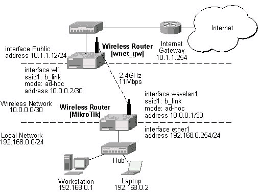
Two possible wireless network configurations are discussed in the following examples:
Point-to-Point Setup with Routing Let us consider the following network setup with two MikroTik Routers having RadioLAN interfaces:The IP addresses assigned to the wireless interface of Router#1 should be from the network 10.1.0.0/30, e.g.:
[MikroTik] ip address> add address 10.1.0.1/30 interface radiolan1
[MikroTik] ip address> print
  # ADDRESS         NETMASK         NETWORK         BROADCAST       INTERFACE
  0 10.1.0.1        255.255.255.252 10.1.0.1        10.1.0.3        radiolan1
  1 10.1.1.12       255.255.255.0   10.1.1.12       10.1.1.255      ether1
[MikroTik] ip address>
The default route should be set to the gateway router 10.1.1.254. A static route should be added for the network 192.168.0.0/24:
[MikroTik] ip route> add gateway 10.1.1.254 interface ether1
[MikroTik] ip route> add dst-address 192.168.0.0/24 gateway 10.1.0.2 \
interface radiolan1
[MikroTik] ip route> print
  # DST-ADDRESS     NETMASK         GATEWAY         PREF-ADDRESS    INTE...
  0 10.1.1.0        255.255.255.0   0.0.0.0         10.1.1.12       ether1  D K
  1 10.1.0.0        255.255.255.252 0.0.0.0         10.1.0.1        radi... D K
  2 192.168.0.0     255.255.255.0   10.1.0.2        0.0.0.0         radi...
  3 0.0.0.0         0.0.0.0         10.1.1.254      0.0.0.0         ether1
[MikroTik] ip route>
For more information about the WaveLAN / ORiNOCO adapter hardware please see the relevant
Users Guides and Technical Reference Manuals in .pdf format from the manufacturer:
Information about configuring the ORiNOCO wireless access point can be found there:
Contents of the Manual
The following topics are covered in this manual:
[MikroTik] system package> print
  # NAME                                             VERSION    BUILD UNINSTALL
  0 routing                                          2.3.15     21    no
  1 snmp                                             2.3.15     15    no
  2 ppp                                              2.3.15     20    no
  3 pptp                                             2.3.15     21    no
  4 pppoe                                            2.3.15     22    no
  5 ssh                                              2.3.15     26    no
  6 system                                           2.3.15     32    no
  7 option                                           2.3.15     20    no
  8 wavelan                                          2.3.15     21    no
[MikroTik] system package>
[[MikroTik] system resource> irq print
IRQ OWNER
1   keyboard                                                                  U
2   APIC                                                                      U
3
4
5
6
7
8
9
10  ether1                                                                    U
11
12
13  FPU                                                                       U
14  IDE 1                                                                     U
[MikroTik] system resource> io print
IO        OWNER
0020-003f APIC
0040-005f timer
0060-006f keyboard
0080-008f DMA
00a0-00bf APIC
00c0-00df DMA
00f0-00ff FPU
01f0-01f7 IDE 1
03c0-03df VGA
03e0-03e1 PCMCIA service
03f6-03f6 IDE 1
6100-611f ether1
[MikroTik] system resource>
Installing the Wireless Adapter
The basic installation steps of the wireless adapter should be as follows:
Loading the Driver for the Wireless Adapter
The WaveLAN / Orinoco PC (PCMCIA) cards do not require a 'manual' driver loading, since they
are recognized automatically by the system and the driver is loaded at the system startup.
If the driver has loaded successfully, there should be two beeps of equal tone,
which should be heard through the PC's speaker while the system startup.
If the second beep has a lower tone than the first one, then the driver could not be loaded,
or, there is no wavelan package installed.
Note! The PC card can be inserted in the PCMCIA-ISA or PCI adapter when the system is running. The wavelan driver is not listed under the list of loaded drivers.
There can be several reasons for a failure to load the driver:
[MikroTik] interface> print
  # NAME                                                    TYPE        MTU
  0 ether1                                                  ether       1500
( 1)wavelan1                                                wavelan     1500
[MikroTik] interface> enable 1
[MikroTik] interface> print
  # NAME                                                    TYPE        MTU
  0 ether1                                                  ether       1500
  1 wavelan1                                                wavelan     1500
[MikroTik] interface>
More configuration and statistics parameters can be found under the '/interface wavelan' menu:
[MikroTik] interface> wavelan
[MikroTik] interface wavelan> print
0   name: wavelan1 mtu: 1500 mac-address: 00:02:2D:07:17:23 channel: 2412MHz
    date-rate: 11Mbit/s mode: ad-hoc ssid: "" client-name: "" key1: ""
    key2: "" key3: "" key4: "" tx-key: key1 encryption: no arp: arp

[MikroTik] interface wavelan>
Argument description:
number - Interface number in the list
name - Interface name
mtu - Maximum Transmit Unit (256...2296 bytes). The default value is 1500 bytes.
mac-address - MAC address of the card. Cannot be changed.
channel - Channel frequency (2412MHz / 2422MHz / ... / 2484MHz)
data-rate - Data rate (11Mbit/s / 1Mbit/s / 2Mbit/s / 5.5Mbit/s / auto)
mode - Operation mode of the card (infrastructure / ad-hoc)
ssid - Service Set Identifier
client-name - Client name
key1 - Encryption key #1
key2 - Encryption key #2
key3 - Encryption key #3
key4 - Encryption key #4
tx-key - Transmit key (key1 / key2 / key3 / key4)
encryption - Encryption (no / yes)
arp - Address Resolution Protocol (disabled / enabled / proxy-arp)
You can monitor the status of the wireless interface:
[MikroTik] interface wavelan> monitor wavelan1
             bssid: 00:00:00:00:00:00
           channel: 2422MHz
         data-rate: 2Mbit/s
              ssid:
    signal-quality: 0
      signal-level: 154
             noise: 154
[MikroTik] interface wavelan>
If the wireless interface card is not registered to an AP, the green status led is blinking fast.
To set the wireless interface for working with an IEEE 802.11b access point (register to the AP), you should set the following parameters:
[MikroTik] interface wavelan> set 0 ssid MT_w_AP
[MikroTik] interface wavelan> monitor wavelan1
             bssid: 00:60:B3:66:C7:40
           channel: 2452MHz
         data-rate: 11Mbit/s
              ssid: MT_w_AP
    signal-quality: 56
      signal-level: 213
             noise: 157
[MikroTik] interface wavelan>
Two possible wireless network configurations are discussed in the following examples:
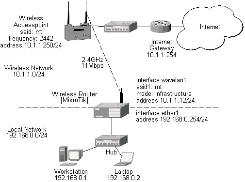
The access point is connected to the wired network's HUB and has IP address from the network 10.1.1.0/24. The minimum configuration required for the AP is:
Reminder! Please note, that the AP is not a router! It has just one network address, and is just like any host on the network. It resembles a wireless-to-Ethernet HUB or bridge. The AP does not route the IP traffic!
The minimum configuration for the MikroTik router's wavelan wireless interface is:
[MikroTik] interface wavelan> set wavelan1 ssid mt
[MikroTik] interface wavelan> monitor wavelan1
             bssid: 00:60:B3:66:C7:40
           channel: 2442MHz
         data-rate: 11Mbit/s
              ssid: mt
    signal-quality: 56
      signal-level: 214
             noise: 158
[MikroTik] interface wavelan>
The channel frequency argument does not have any meaning, since the
frequency of the AP is used.
IP Network Configuration
The IP addresses assigned to the wireless interface should be from the network 10.1.1.0/24, e.g.:
[MikroTik] ip address> add address 10.1.1.12/24 interface wavelan1
[MikroTik] ip address> add address 192.168.0.254/24 interface ether1
[MikroTik] ip address> print
  # ADDRESS         NETMASK         NETWORK         BROADCAST       INTERFACE
  0 10.1.1.12       255.255.255.0   10.1.1.12       10.1.1.255      wavelan1
  1 192.168.0.254   255.255.255.0   192.168.0.254   192.168.0.255   ether1
[MikroTik] ip address>
The default route should be set to the gateway router 10.1.1.254 (not the AP 10.1.1.250 !):
[MikroTik] ip route> print
  # DST-ADDRESS     NETMASK         GATEWAY         PREF-ADDRESS    INTE...
  0 10.1.1.0        255.255.255.0   0.0.0.0         10.1.1.12       wave... D K
  1 192.168.0.0     255.255.255.0   0.0.0.0         192.168.0.254   ether1  D K
  2 0.0.0.0         0.0.0.0         10.1.1.254      0.0.0.0         wave...
[MikroTik] ip route>
This document applies to the V2.4 of the MikroTik RouterOS
For more information about adapter hardware please see the relevant
Users Guides and Technical Reference Manuals of the hardware manufacturers.
The MikroTik RouterOS supports the PrismII chipset based wireless adapter cards for working both as wireless clients (station mode) and wireless access points (access point mode).
[MikroTik] > sys package print
  # NAME                   VERSION               BUILD-TIME           UNINSTALL
  0 routing                2.4rc6                aug/06/2001 15:56:22 no
  1 snmp                   2.4rc6                aug/06/2001 15:56:24 no
  2 ppp                    2.4rc6                aug/06/2001 15:56:37 no
  3 pptp                   2.4rc6                aug/06/2001 15:56:47 no
  4 pppoe                  2.4rc6                aug/06/2001 15:56:53 no
  5 ssh                    2.4rc6                aug/06/2001 15:58:11 no
  6 system                 2.4rc6                aug/06/2001 15:56:04 no
  7 prism                  2.4rc6                aug/06/2001 15:58:54 no
[MikroTik] >
The 2.4GHz Wireless Feature License enables only the station mode of the Prism II card. To enable the access point mode, additionally the Wireless AP Feature License is required.
The MikroTik RouterOS supports as many PrismII chipset based cards as many free resources are on your system, i.e., IRQs and adapter slots. One license is valid for all cards on your system.
[MikroTik] > system resource irq print
 IRQ USED OWNER
 1   yes  keyboard
 2   yes  APIC
 3   no
 4   yes  serial port
 5   no
 6   no
 7   no
 8   no
 9   yes  ether1
 10  no
 11  no
 12  no
 13  yes  FPU
 14  yes  IDE 1
[MikroTik] > system resource io print
 PORT-RANGE            OWNER
 32-63                 APIC
 64-95                 timer
 96-111                keyboard
 128-143               DMA
 160-191               APIC
 192-223               DMA
 240-255               FPU
 496-503               IDE 1
 760-767               serial port
 960-991               VGA
 992-993               PCMCIA service
 1014-1014             IDE 1
 1016-1023             serial port
 61184-61439           ether1
 64512-64519           IDE 1
 64520-64527           IDE 2
 64528-64639           [CS5530]
[MikroTik] >
There can be several reasons for a failure to load the driver, for example:
[MikroTik] > interface print
Flags: X - disabled, D - dynamic
  #   NAME                 MTU   TYPE
  0   ether1               1500  ether
  2 X prism1               1500  prism
[MikroTik] > interface enable 1
[MikroTik] > interface set 1 name=wireless
[MikroTik] > interface print
Flags: X - disabled, D - dynamic
  #   NAME                 MTU   TYPE
  0   ether1               1500  ether
  1   wireless             1500  prism
[MikroTik] >
More configuration and statistics parameters can be found under the '/interface prism' menu:
[MikroTik] interface prism> print
Flags: X - disabled
  0   name=wireless mtu=1500 mac-address=00:03:C0:00:06:72 arp=enabled
      mode=station frequency=2412MHz ssid=abc client-name=""
      max-associations=250 hide-ssid=no supported-rates=1-11 basic-rates=1-2
      fragmentation-threshold=2346 rts-threshold=2432
      default-access-action=allow

[MikroTik] interface prism>
Argument description:
number - Interface number in the list
name - Interface name (same as for other interfaces)
mtu - Maximum transfer unit (same as for other interfaces)
mac-address - MAC address of card. In AP mode this will also be BSSID of BSS.
arp - ARP mode (same as for ethernet interfaces)
mode - (station|access-point). If station - card works as station, if access-point, card works as access point. After mode is changed from access-point to station, for station mode to activate, have to reboot (changing back to AP mode will work fine). Change from station to AP can be done without rebooting.
frequency - Frequency that AP will use to create BSS
ssid - Service Set Identifier. In station mode - ssid to connect to, in AP mode - ssid to use when creating BSS (this can not be left blank, because AP needs ssid to work, but in station mode cards hang up without ssid.
client-name - Client name
max-associations - meaningless for station. For AP means how many stations can be associated at the same time (min: 1, max: 500)
hide-ssid - meaningless for station. For AP tells that SSID should not be transmitted in beacon frames (so none can read ssid when sniffing radio), and that AP should not answer probe requests that do not have our ssid in them. Basically this means that if this setting is set to "yes", every client that wants to connect to this AP has to have correct ssid configured.
supported-rates - For both - station and AP - rates at which this node will work.
basic-rates - Meaningless for station. For AP - rates that every client that plans to connect to this AP should be able to work at.
fragmentation-threshold - for both STA and AP - bigger packets than this value will be fragmented before transmission (min: 256, max: 2346)
rts-threshold - for both STA and AP - bigger packets than this value will be transmitted using RTS/CTS medium reservation method. This medium reservation ensures that no other radios transmit at this time (min: 0, max: 2432)
default-access-action - (allow|deny) - meaningless for STA, for AP - what to do with client that wants to associate, but it is not in the access-list.
You can monitor the status of the wireless interface:
[MikroTik] interface prism> monitor 0
       signal-quality: 0
         signal-level: 27
          noise-level: 27
         current-rate: 2
               status: disconnected

[MikroTik] interface prism>
Station Mode Configuration
To set the wireless interface for working with an IEEE 802.11b access point (register to the AP),
you should set the following parameters:
[MikroTik] interface prism> set 0 ssid=mt
[MikroTik] interface prism> monitor 0
                bssid: 00:40:96:37:71:1E
    current-frequency: 2442MHz
       signal-quality: 92
         signal-level: 183
          noise-level: 0
         current-rate: 8
               status: connected

[MikroTik] interface prism>
If the wireless interface card is registered to an AP.
Access Point Mode Configuration
To set the wireless interface for working as an IEEE 802.11b access point (register clients),
you should set the following parameters:
All other parameters can be left as default. To configure the wireless interface for working as an access point with ssid "mt" and use the frequency 2442MHz, it is enough to enter the command:
[MikroTik] interface prism> set 0 mode=access-point ssid=mt frequency=2442MHz
[MikroTik] interface prism> monitor
                bssid: 00:03:C0:00:06:72
    current-frequency: 2442MHz
               status: ap-mode

[MikroTik] interface prism>
To see the list of all clients currently registered to all configured APs,
[MikroTik] interface prism> registration-table print
  # INT MAC-ADDRESS       SIGNAL     SILENCE    RATE       UPTIME
  0 wir 00:40:96:37:71:1E 183        0          11         00:03:32
  1 wir 00:40:96:29:02:88                                  00:01:15
[MikroTik] interface prism>
Argument description for the registration-table entry:
mac-address - mac address of the registered client
interface - interface that client is registered to
signal - signal level
silence - silence level
rate - current rate
uptime - how long client is connected
The monitor command gives additional per-client statistics:
[MikroTik] interface prism> registration-table monitor 0
        packets: 13,2
          bytes: 0,616
            bps: 0.0bps/0.0bps,0.0bps/4.10kbps
            pps: 0/1,0/1
         signal: 171/186/195
        silence: 0/0/0
           rate: 11/11/11
    last-update: 00:00:02
         uptime: 00:09:01

[MikroTik] interface prism>
Ta add an access list entry for MAC address 00:40:96:37:71:1E, use command:
[MikroTik] interface prism access-list> add allow=yes interface=wireless \
mac-address=00:40:96:37:71:1E
[MikroTik] interface prism access-list> print
Flags: X - disabled, I - invalid
  #   MAC-ADDRESS       ALLOW INTERFACE
  0   00:40:96:37:71:1E yes   wireless
[MikroTik] interface prism access-list>
Argument description:
allow - (yes|no) - accept this client when it tries to connect or not
interface - AP interface
mac-address - MAC address of the client
If you have default access action for the interface set to 'allow', you can disallow this node to register at the AP's interface 'wireless' by changing the 'allow' argument value to 'no':
[MikroTik] interface prism access-list> .. print
Flags: X - disabled
  0   name=wireless mtu=1500 mac-address=00:03:C0:00:06:72 arp=enabled
      mode=access-point frequency=2442MHz ssid=mt client-name=MT_Prism
      max-associations=250 hide-ssid=no supported-rates=1-11 basic-rates=1-2
      fragmentation-threshold=2346 rts-threshold=2432
      default-access-action=allow

[MikroTik] interface prism access-list> set 0 allow=no
[MikroTik] interface prism access-list> print
Flags: X - disabled, I - invalid
  #   MAC-ADDRESS       ALLOW INTERFACE
  0   00:40:96:37:71:1E no    wireless
[MikroTik] interface prism access-list>
Thus, all nodes except this one will be able to register to the interface 'wireless'.
If you have default access action for the interface set to 'deny', you can allow this node to register at the AP's interface 'wireless' by changing the 'allow' argument value to back 'yes':
[MikroTik] interface prism access-list> .. print
Flags: X - disabled
  0   name=wireless mtu=1500 mac-address=00:03:C0:00:06:72 arp=enabled
      mode=access-point frequency=2442MHz ssid=mt client-name=MT_Prism
      max-associations=250 hide-ssid=no supported-rates=1-11 basic-rates=1-2
      fragmentation-threshold=2346 rts-threshold=2432
      default-access-action=deny

[MikroTik] interface prism access-list> set 0 allow=yes
[MikroTik] interface prism access-list> print
Flags: X - disabled, I - invalid
  #   MAC-ADDRESS       ALLOW INTERFACE
  0   00:40:96:37:71:1E yes   wireless
[MikroTik] interface prism access-list>
Two possible wireless network configurations are discussed in the following examples:
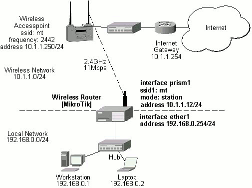
The access point is connected to the wired network's HUB and has IP address from the network 10.1.1.0/24. The minimum configuration required for the AP is:
Reminder! Please note, that the AP is not a router! It has just one network address, and is just like any host on the network. It resembles a wireless-to-Ethernet HUB or bridge. The AP does not route the IP traffic!
The minimum configuration for the MikroTik router's prism wireless interface is:
[MikroTik] interface prism> set 0 ssid=mt
[MikroTik] interface prism> monitor 0
                bssid: 00:40:96:37:71:1E
    current-frequency: 2442MHz
       signal-quality: 92
         signal-level: 195
          noise-level: 0
         current-rate: 8
               status: connected

[MikroTik] interface prism>
The IP addresses assigned to the wireless interface should be from the network 10.1.1.0/24, e.g.:
[MikroTik] ip address> add address=10.1.1.12/24 interface=prism1
[MikroTik] ip address> print
Flags: X - disabled, I - invalid, D - dynamic
  #   ADDRESS            NETWORK         BROADCAST       INTERFACE
  0   10.1.1.12/24       10.1.1.0        10.1.1.255      prism1
  1   192.168.0.254/24   192.168.0.254   192.168.0.254   ether1
[MikroTik] ip address>
The default route should be set to the gateway router 10.1.1.254 (not the AP 10.1.1.250 !):
[MikroTik] ip route> add gateway=10.1.1.254
[MikroTik] ip route> print
Flags: X - disabled, I - invalid, D - dynamic, R - rejected
  #    TYPE           DST-ADDRESS        GATEWAY        DISTANCE INTERFACE
  0    static         0.0.0.0/0          10.1.1.254     1        prism1
  1 D  connect        10.1.1.0/24        0.0.0.0        0        prism1
  2 D  connect        192.168.0.254/24   0.0.0.0        0        ether1
[MikroTik] ip route>
Note! You cannot use the bridging function between the prism and ethernet interfaces, if the prism interface is in the station mode. The bridge does not work in this case!
| to the contents |