
PPP and Asynchronous Interfaces
| Document revision: | 1.3 (October 31, 2007, 13:15 GMT) |
| Applies to: | V3.0 |
General Information
Summary
PPP (Point-to-Point Protocol) provides a method for transmitting datagrams over serial point-to-point links. Physically it relies on COM1 and COM2 ports from standard PC hardware configurations. These appear as serial0 and serial1 automatically. You can add more serial ports to use the router for a modem pool using these adapters:
- MOXA (http://www.moxa.com) Smartio CP-132 2-port PCI multiport asynchronous board with maximum of 8 ports (4 cards)
- MOXA (http://www.moxa.com) Smartio C104H, CP-114 or CT-114 4-port PCI multiport asynchronous board with maximum of 16 ports (4 cards)
- MOXA (http://www.moxa.com) Smartio C168H, CP-168H or CP-168U 8-port PCI multiport asynchronous board with maximum of 32 ports (4 cards)
- Cyclades (http://www.cyclades.com) Cyclom-Y Series 4 to 32 port PCI multiport asynchronous board with maximum of 128 ports (4 cards)
- Cyclades (http://www.cyclades.com) Cyclades-Z Series 16 to 64 port PCI multiport asynchronous board with maximum of 256 ports (4 cards)
- TCL (http://www.thetcl.com) DataBooster 4 or 8 port High Speed Buffered PCI Communication Controllers
Specifications
Packages required: pppLicense required: Level1
Submenu level: /interface ppp-client, /interface ppp-server
Standards and Technologies: PPP (RFC 1661)
Hardware usage: Not significant
Additional Resources
Serial Port Configuration
Submenu level: /portProperty Description
baud-rate (integer; default: 9600) - data rate of the portdata-bits (7 | 8; default: 8) - number of bits per character transmittedflow-control (none | hardware | xon-xoff; default: hardware) - flow control methodname (name; default: serialN) - port nameparity (none | even | odd; default: none) - character parity check methodstop-bits (1 | 2; default: 1) - number of stop bits after each character transmittedused-by (read-only: text) - shows the user (if any) of the port. Only unused ports can be used in PPP setupNotes
Keep in mind that baud-rate, data-bits, parity, stop-bits and flow control parameters must be the same for both communicating parties.
Example
[admin@MikroTik] > /port print
  # NAME                             USED-BY                          BAUD-RATE
  0 serial0                          Serial Console                   9600
  1 databooster1                                                      9600
  2 databooster2                                                      9600
  3 databooster3                                                      9600
  4 databooster4                                                      9600
  5 databooster5                                                      9600
  6 databooster6                                                      9600
  7 databooster7                                                      9600
  8 databooster8                                                      9600
  9 cycladesA1                                                        9600
 10 cycladesA2                                                        9600
 11 cycladesA3                                                        9600
 12 cycladesA4                                                        9600
 13 cycladesA5                                                        9600
 14 cycladesA6                                                        9600
 15 cycladesA7                                                        9600
 16 cycladesA8                                                        9600
[admin@MikroTik] > set 9 baud-rate=38400
[admin@MikroTik] >
PPP Server Setup
Submenu level: /interface ppp-serverDescription
PPP server provides a remode connection service for users. When dialing in, the users can be authenticated locally using the local user database in the /user menu, or at the RADIUS server specified in the /ip ppp settings.
Property Description
authentication (multiple choice: mschap2, mschap1, chap, pap; default: mschap2, mschap1, chap, pap) - authentication protocol(s)max-mru (integer; default: 1500) - maximum value of MRU (Maximum Receive Unit) allowed on this link. Largest packet that can be receivedmax-mtu (integer; default: 1500) - maximum value of MTU (Maximum Transmission Unit) allowed on this link. Maximum packet size to be transmittedmodem-init (text; default: "") - modem initialization string. For example, you may use "s11=40" to improve dialing speedmrru (integer) - maximum packet size that can be received on the link. If packet is bigger than tunnel MTU, it will be split into multiple packets. That way it is possible to send full size (1500 or even 1514) packets over PPTP or L2TP tunnels.Notes
Specifying MRRU means enabling MP (Multilink PPP) over single link. This protocol is used to split big packets into smaller ones. Under Windows it can be enabled in Networking tag, Settings button, "Negotiate multi-link for single link connections". Their MRRU is hardcoded to 1614. This setting is usefull to overcome PathMTU discovery failures. The MP should be enabled on both peers.
Example
You can add a PPP server using the add command:
[admin@MikroTik] interface ppp-server> add name=test port=serial1
[admin@MikroTik] interface ppp-server> print
Flags: X - disabled, R - running
  0 X  name="test" max-mtu=1500 max-mru=1500 mrru=disabled port=serial1
       authentication=pap,chap,mschap1,mschap2 profile=default modem-init=""
       ring-count=1 null-modem=no
[admin@MikroTik] interface ppp-server> enable 0
[admin@MikroTik] interface ppp-server> monitor test
            status: "waiting for call..."

[admin@MikroTik] interface ppp-server>
PPP Client Setup
Submenu level: /interface ppp-clientDescription
The section describes PPP clients configuration routines.
Property Description
add-default-route (yes | no; default: no) - add PPP remote address as a default routeallow (multiple choice: mschap2, mschap1, chap, pap; default: mschap2, mschap1, chap, pap) - the protocol to allow the client to use for authenticationdial-command (text; default: "ATDT") - AT dial command to use. The default one sets tone diling modedial-on-demand (yes | no; default: no) - enable/disable dial on demandmax-mru (integer; default: 1500) - maximum value of MRU (Maximum Receive Unit) allowed on this link. Largest packet that can be receivedmax-mtu (integer; default: 1500) - maximum value of MTU (Maximum Transmission Unit) allowed on this link. Maximum packet size to be transmittedmodem-init (text; default: "") - modem initialization strings. You may use "s11=40" to improve dialing speedmrru (integer) - maximum packet size that can be received on the link. If packet is bigger than tunnel MTU, it will be split into multiple packets. That way it is possible to send full size (1500 or even 1514) packets over PPTP or L2TP tunnels.Notes
Additional client profiles must be configured on the server side for clients to accomplish logon procedure. For more information see Related Documents section.
PPP client profiles must match at least partially (local-address and values related to encryption should match) with corresponding remote server values.
Example
You can add a PPP client using the add command:
[admin@MikroTik] interface ppp-client> add name=test user=test port=serial1 \
\... add-default-route=yes
[admin@MikroTik] interface ppp-client> print
Flags: X - disabled, R - running
  0 X  name="test" mtu=1500 mru=1500 port=serial1 user="test" password=""
       profile=default phone="" tone-dial=yes modem-init="" null-modem=no
       dial-on-demand=no add-default-route=yes use-peer-dns=no

[admin@MikroTik] interface ppp-client> enable 0
[admin@MikroTik] interface ppp-client> monitor test
[admin@MikroTik] interface ppp-client> monitor 0
           status: "dialing out..."

[admin@MikroTik] interface ppp-client>
PPP Application Example
Client - Server Setup
In this example we will consider the following network setup:
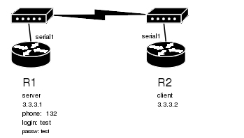
For a typical server setup we need to add one user to the R1 and configure the PPP server.
[admin@MikroTik] ppp secret> add name=test password=test local-address=3.3.3.1 \
\... remote-address=3.3.3.2
[admin@MikroTik] ppp secret> print
Flags: X - disabled
  0   name="test" service=any caller-id="" password="test" profile=default
      local-address=3.3.3.1 remote-address=3.3.3.2 routes=""

[admin@MikroTik] ppp secret> /int ppp-server
[admin@MikroTik] interface ppp-server> add port=serial1 disabled=no
[admin@MikroTik] interface ppp-server> print
Flags: X - disabled, R - running
  0    name="ppp-in1" mtu=1500 mru=1500 port=serial1
       authentication=mschap2,mschap1,chap,pap profile=default modem-init=""
       ring-count=1 null-modem=no

[admin@MikroTik] interface ppp-server>
Now we need to setup the client to connect to the server:
[admin@MikroTik] interface ppp-client> add port=serial1 user=test password=test \
\... phone=132
[admin@MikroTik] interface ppp-client> print
Flags: X - disabled, R - running
  0 X  name="ppp-out1" mtu=1500 mru=1500 port=serial1 user="test"
       password="test" profile=default phone="132" tone-dial=yes
       modem-init="" null-modem=no dial-on-demand=no add-default-route=no
       use-peer-dns=no

[admin@MikroTik] interface ppp-client> enable 0

After a short duration of time the routers will be able to ping each other:
[admin@MikroTik] interface ppp-client> /ping 3.3.3.1
3.3.3.1 64 byte ping: ttl=64 time=43 ms
3.3.3.1 64 byte ping: ttl=64 time=11 ms
3.3.3.1 64 byte ping: ttl=64 time=12 ms
3.3.3.1 64 byte ping: ttl=64 time=11 ms
4 packets transmitted, 4 packets received, 0% packet loss
round-trip min/avg/max = 11/19.2/43 ms
[admin@MikroTik] interface ppp-client>