state-changes (read-only: integer) - number of state changes of the connection
ls-retransmits (read-only: integer) - number of Link State retransmits
ls-requests (read-only: integer) - number of Link State requests
db-summaries (read-only: integer) - number of records in link-state database advertised by the neighbour
dr-id (read-only: IP address) - router id of designated router for this neighbor
backup-dr-id (read-only: IP address) - router id of backup designated router for this neighbor
Notes
The list also shows the router itself in this list.Example
The following text can be viewed just after adding an OSPF network:
[admin@MikroTik] routing ospf> neighbor print
 router-id=10.0.0.204 address=10.0.0.204 priority=1 state="2-Way"
    state-changes=0 ls-retransmits=0 ls-requests=0 db-summaries=0
    dr-id=0.0.0.0 backup-dr-id=0.0.0.0

[admin@MikroTik] routing ospf>
An Example of Running OSPF
After configuring OSPF on a number of interconnected routers, dynamic routes should appear in the ip route print list:
[admin@MikroTik] ip route> print
Flags: X - disabled, I - invalid, D - dynamic, J - rejected,
C - connect, S - static, R - rip, O - ospf, B - bgp
    #    DST-ADDRESS        G GATEWAY         DISTANCE INTERFACE
    0  S ;;; our default gateway
         0.0.0.0/0          r 10.0.0.1        1        ether1
    1 DC 192.168.0.0/24     r 0.0.0.0         0        ether4
    2 DO 10.10.10.0/24      r 10.10.1.1       110      ether2
    3 DC 10.10.1.0/24       r 0.0.0.0         0        ether2
    4 DC 10.0.0.0/24        r 0.0.0.0         0        ether1
[admin@MikroTik] routing ospf>
In this case, we have one one route connected through 10.10.1.1 router (item #2).
As current router distributes its routes too (including default one), in 10.10.1.1 router we have:
[admin@Remote] > ip route print
Flags: X - disabled, I - invalid, D - dynamic, J - rejected,
C - connect, S - static, R - rip, O - ospf, B - bgp
    #    DST-ADDRESS        G GATEWAY         DISTANCE INTERFACE
    0 DO 0.0.0.0/0          r 10.10.1.2       110      ether1
    1 DO 192.168.0.0/24     r 10.10.1.2       110      ether1
    2 DC 10.10.10.0/24      r 0.0.0.0         0        radiolan1
    3 DC 10.10.1.0/24       r 0.0.0.0         0        ether1
    4 DO 10.5.5.0/24        r 10.10.1.2       110      ether1
    5 DO 10.0.0.0/24        r 10.10.1.2       110      ether1
[admin@Remote] >
OSPF Troubleshooting
- OSPF does not work on point-to-point link (PPP, PPPoE, PPTP)
Make sure you include the remote address of the point-to-point link into the /router ospf network record. For example, if you have[admin@MikroTik] ip address> print Flags: X - disabled, I - invalid, D - dynamic # ADDRESS NETWORK BROADCAST INTERFACE 0 10.7.1.3/24 10.7.1.0 10.7.1.255 backbone 1 192.168.223.55/25 192.168.223.0 192.168.223.127 aironet 2 D 10.2.0.7/32 10.2.0.8 0.0.0.0 pptp-out1 [admin@MikroTik] ip address>
Use /router ospf network add network=10.2.0.8/32 area=backbone.
OSPF Backup without using Tunnel
This example shows how to use OSPF for backup purposes, if you are controlling all the involved routers, and you can run OSPF on them.
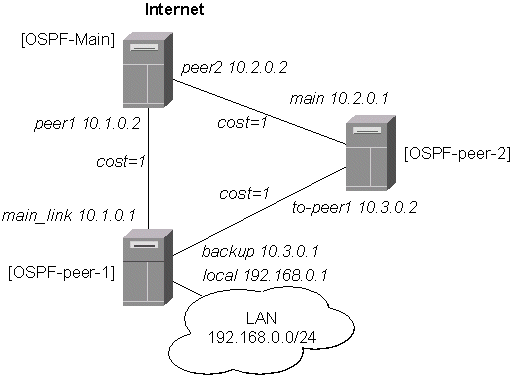
Let us assume that the link between the routers OSPF-Main and OSPF-peer-1 is the main one. If it goes down, we want the traffic switch over to the link going through the router OSPF-peer-2.
For this:
- We introduce an OSPF area with area ID=0.0.0.1, which includes all three routers shown on the diagram.
- Only the OSPF-Main router will have the default route configured. Its interfaces peer1 and peer2 will be configured for the OSPF protocol. The interface main_gw will not be used for distributing the OSPF routing information.
- The routers OSPF-peer-1 and OSPF-peer-2 will distribute their connected route information, and receive the default route using the OSPF protocol.
OSPF_Main Router Setup
The IP address configuration of the [OSPF_Main] router is as follows:
[admin@OSPF-Main] interface> /ip address print
Flags: X - disabled, I - invalid, D - dynamic
  #   ADDRESS            NETWORK         BROADCAST       INTERFACE
  0   10.0.0.214/24      10.0.0.0        10.0.0.255      main_gw
  1   10.1.0.2/24        10.1.0.0        10.1.0.255      peer1
  2   10.2.0.2/24        10.2.0.0        10.2.0.255      peer2
[admin@OSPF-Main] interface>
OSPF settings:
[admin@OSPF-Main] > routing ospf print
                 router-id: 0.0.0.0
        distribute-default: if-installed-as-type-2
    redistribute-connected: as-type-1
       redistribute-static: as-type-2
          redistribute-rip: no
          redistribute-bgp: no
            metric-default: 1
          metric-connected: 0
             metric-static: 0
                metric-rip: 0
                metric-bgp: 0

[admin@OSPF-Main] > routing ospf area print
Flags: X - disabled
  0   name=backbone area-id=0.0.0.0 default-cost=0 stub=no
      authentication=none

  1   name=local_10 area-id=0.0.0.1 default-cost=0 stub=no
      authentication=none

[admin@OSPF-Main] > routing ospf network print
Flags: X - disabled
  #   NETWORK            AREA
  0   10.1.0.0/24        local_10
  1   10.2.0.0/24        local_10
[admin@OSPF-Main] >
OSPF-peer-1 Router Setup
The IP address configuration of the [OSPF-peer-1] router is as follows:
[admin@OSPF-peer-1] > ip address print
Flags: X - disabled, I - invalid, D - dynamic
  #   ADDRESS            NETWORK         BROADCAST       INTERFACE
  0   10.1.0.1/24        10.1.0.0        10.1.0.255      main_link
  1   10.3.0.1/24        10.3.0.0        10.3.0.255      backup
  2   192.168.0.1/24     192.168.0.0     192.168.0.255   local
[admin@OSPF-peer-1] >
OSPF settings:
[admin@OSPF-peer-1] > routing ospf print
                 router-id: 0.0.0.0
        distribute-default: never
    redistribute-connected: as-type-1
       redistribute-static: no
          redistribute-rip: no
          redistribute-bgp: no
            metric-default: 1
          metric-connected: 0
             metric-static: 0
                metric-rip: 0
                metric-bgp: 0
[admin@OSPF-peer-1] > routing ospf area print
Flags: X - disabled
  0   name=backbone area-id=0.0.0.0 default-cost=0 stub=no
      authentication=none

  1   name=local_10 area-id=0.0.0.1 default-cost=0 stub=no
      authentication=none

[admin@OSPF-peer-1] > routing ospf network print
Flags: X - disabled
  #   NETWORK            AREA
  0   10.3.0.0/24        local_10
  1   10.1.0.0/24        local_10
[admin@OSPF-peer-1] >
OSPF-peer-2 Router Setup
The IP address configuration of the [OSPF-peer-2] router is as follows:
[admin@OSPF-peer-2] > ip address print
Flags: X - disabled, I - invalid, D - dynamic
  #   ADDRESS            NETWORK         BROADCAST       INTERFACE
  0   10.2.0.1/24        10.2.0.0        10.2.0.255      main
  1   10.3.0.2/24        10.3.0.0        10.3.0.255      to-peer1
[admin@OSPF-peer-2] >
OSPF settings:
[admin@OSPF-peer-2] > routing ospf print
                 router-id: 0.0.0.0
        distribute-default: never
    redistribute-connected: as-type-1
       redistribute-static: no
          redistribute-rip: no
          redistribute-bgp: no
            metric-default: 1
          metric-connected: 0
             metric-static: 0
                metric-rip: 0
                metric-bgp: 0
[admin@OSPF-peer-2] > routing ospf area print
Flags: X - disabled
  0   name=backbone area-id=0.0.0.0 default-cost=0 stub=no
      authentication=none

  1   name=local_10 area-id=0.0.0.1 default-cost=0 stub=no
      authentication=none

[admin@OSPF-peer-2] > routing ospf network print
Flags: X - disabled
  #   NETWORK            AREA
  0   10.2.0.0/24        local_10
  1   10.3.0.0/24        local_10
[admin@OSPF-peer-2] >
Routing Tables
After the three routers have been set up as described above, and the links between them are operational, the routing tables of the three routers should look as follows:
On the main OSPF router:
[admin@OSPF-Main] > ip route print
Flags: X - disabled, I - invalid, D - dynamic, J - rejected,
C - connect, S - static, R - rip, O - ospf, B - bgp
    #    DST-ADDRESS        G GATEWAY         DISTANCE INTERFACE
    0  S 0.0.0.0/0          r 10.0.0.1        1        main_gw
    1 DO 192.168.0.0/24     r 10.1.0.1        110      peer1
    2 DC 10.2.0.0/24        r 0.0.0.0         0        peer2
    3 DO 10.3.0.0/24        r 10.2.0.1        110      peer2
                            r 10.1.0.1                 peer1
    4 DC 10.1.0.0/24        r 0.0.0.0         0        peer1
    5 DC 10.0.0.0/24        r 0.0.0.0         0        main_gw

[admin@OSPF-Main] >
On the Peer 1:
[admin@OSPF-peer-1] > ip route print
Flags: X - disabled, I - invalid, D - dynamic, J - rejected,
C - connect, S - static, R - rip, O - ospf, B - bgp
    #    DST-ADDRESS        G GATEWAY         DISTANCE INTERFACE
    0 DO 0.0.0.0/0          r 10.1.0.2        110      main_link
    1 DC 192.168.0.0/24     r 0.0.0.0         0        local
    2 DO 10.2.0.0/24        r 10.1.0.2        110      main_link
                            r 10.3.0.2                 backup
    3 DC 10.3.0.0/24        r 0.0.0.0         0        backup
    4 DC 10.1.0.0/24        r 0.0.0.0         0        main_link
    5 DO 10.0.0.0/24        r 10.1.0.2        110      main_link
[admin@OSPF-peer-1] >
On the Peer 2:
[admin@OSPF-peer-2] > ip route print
Flags: X - disabled, I - invalid, D - dynamic, J - rejected,
C - connect, S - static, R - rip, O - ospf, B - bgp
    #    DST-ADDRESS        G GATEWAY         DISTANCE INTERFACE
    0 DO 0.0.0.0/0          r 10.2.0.2        110      main
    1 DO 192.168.0.0/24     r 10.3.0.1        110      to-peer1
    2 DC 10.2.0.0/24        r 0.0.0.0         0        main
    3 DC 10.3.0.0/24        r 0.0.0.0         0        to-peer1
    4 DO 10.1.0.0/24        r 10.3.0.1        110      to-peer1
                            r 10.2.0.2                 main
    5 DO 10.0.0.0/24        r 10.2.0.2        110      main
[admin@OSPF-peer-2] >
Please note the three equal cost multipath routes (multiple gateways for one destination) in this setup. They have been created by the OSPF, because there is equal cost to go, for example, from the router OSPF-peer-2 to the network 10.1.0.0/24.
The cost is calculated as the sum of costs over each hop to the destination. Unless this is not specially desired, we may want to avoid such situations, i.e., and adjust the cost settings for the interfaces (links) accordingly.
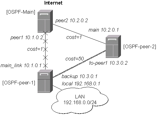
Routing Tables with Revised Link Cost
Let us assume, that the link between the routers OSPF-peer-1 and OSPF-peer-2 has a higher cost (might be slower, we have to pay more for the traffic through it, etc.). Since we have left all ospf interface cost settings as default (cost=1), we need to change the following settings:
[admin@OSPF-peer-1] > routing ospf interface add interface=backup cost=50
[admin@OSPF-peer-2] > routing ospf interface add interface=to-peer2 cost=50
The revised network diagram:

After changing the cost settings, we have only one equal cost multipath route left - to the network 10.3.0.0/24 from the OSPF-Main router:
On the main OSPF router:
[admin@OSPF-Main] > ip route print
Flags: X - disabled, I - invalid, D - dynamic, J - rejected,
C - connect, S - static, R - rip, O - ospf, B - bgp
    #    DST-ADDRESS        G GATEWAY         DISTANCE INTERFACE
    0  S 0.0.0.0/0          r 10.0.0.1        1        main_gw
    1 DO 192.168.0.0/24     r 10.1.0.1        110      peer1
    2 DC 10.2.0.0/24        r 0.0.0.0         0        peer2
    3 DO 10.3.0.0/24        r 10.2.0.1        110      peer2
                            r 10.1.0.1                 peer1
    4 DC 10.1.0.0/24        r 0.0.0.0         0        peer1
    5 DC 10.0.0.0/24        r 0.0.0.0         0        main_gw

[admin@OSPF-Main] >
On the Peer 1:
[admin@OSPF-peer-1] > ip route print
Flags: X - disabled, I - invalid, D - dynamic, J - rejected,
C - connect, S - static, R - rip, O - ospf, B - bgp
    #    DST-ADDRESS        G GATEWAY         DISTANCE INTERFACE
    0 DO 0.0.0.0/0          r 10.1.0.2        110      main_link
    1 DC 192.168.0.0/24     r 0.0.0.0         0        local
    2 DO 10.2.0.0/24        r 10.1.0.2        110      main_link
    3 DC 10.3.0.0/24        r 0.0.0.0         0        backup
    4 DC 10.1.0.0/24        r 0.0.0.0         0        main_link
    5 DO 10.0.0.0/24        r 10.1.0.2        110      main_link
[admin@OSPF-peer-1] >
On the Peer 2:
[admin@OSPF-peer-2] > ip route print
Flags: X - disabled, I - invalid, D - dynamic, J - rejected,
C - connect, S - static, R - rip, O - ospf, B - bgp
    #    DST-ADDRESS        G GATEWAY         DISTANCE INTERFACE
    0 DO 0.0.0.0/0          r 10.2.0.2        110      main
    1 DO 192.168.0.0/24     r 10.3.0.1        110      to-peer1
    2 DC 10.2.0.0/24        r 0.0.0.0         0        main
    3 DC 10.3.0.0/24        r 0.0.0.0         0        to-peer1
    4 DO 10.1.0.0/24        r 10.2.0.2        110      main
    5 DO 10.0.0.0/24        r 10.2.0.2        110      main
[admin@OSPF-peer-2] >
Functioning of the Backup
If the link between routers OSPF-Main and OSPF-peer-1 goes down, we have the following situation:
The OSPF routing changes as follows:
On the main OSPF router:
[admin@OSPF-Main] > ip route print
Flags: X - disabled, I - invalid, D - dynamic, J - rejected,
C - connect, S - static, R - rip, O - ospf, B - bgp
    #    DST-ADDRESS        G GATEWAY         DISTANCE INTERFACE
    0  S 0.0.0.0/0          r 10.0.0.1        1        main_gw
    1 DO 192.168.0.0/24     r 10.2.0.1        110      peer2
    2 DC 10.2.0.0/24        r 0.0.0.0         0        peer2
    3 DO 10.3.0.0/24        r 10.2.0.1        110      peer2
    4 DC 10.1.0.0/24        r 0.0.0.0         0        peer1
    5 DC 10.0.0.0/24        r 0.0.0.0         0        main_gw

[admin@OSPF-Main] >
On the Peer 1:
[admin@OSPF-peer-1] > ip route print
Flags: X - disabled, I - invalid, D - dynamic, J - rejected,
C - connect, S - static, R - rip, O - ospf, B - bgp
    #    DST-ADDRESS        G GATEWAY         DISTANCE INTERFACE
    0 DO 0.0.0.0/0          r 10.3.0.2        110      backup
    1 DC 192.168.0.0/24     r 0.0.0.0         0        local
    2 DO 10.2.0.0/24        r 10.3.0.2        110      backup
    3 DC 10.3.0.0/24        r 0.0.0.0         0        backup
    4 DC 10.1.0.0/24        r 0.0.0.0         0        main_link
    5 DO 10.0.0.0/24        r 10.3.0.2        110      backup
[admin@OSPF-peer-1] >
On the Peer 2:
[admin@OSPF-peer-2] > ip route print
Flags: X - disabled, I - invalid, D - dynamic, J - rejected,
C - connect, S - static, R - rip, O - ospf, B - bgp
    #    DST-ADDRESS        G GATEWAY         DISTANCE INTERFACE
    0 DO 0.0.0.0/0          r 10.2.0.2        110      main
    1 DO 192.168.0.0/24     r 10.3.0.1        110      to-peer1
    2 DC 10.2.0.0/24        r 0.0.0.0         0        main
    3 DC 10.3.0.0/24        r 0.0.0.0         0        to-peer1
    4 DO 10.1.0.0/24        r 10.2.0.2        110      main
    5 DO 10.0.0.0/24        r 10.2.0.2        110      main
[admin@OSPF-peer-2] >
The change of the routing takes approximately 40 seconds (the hello-interval setting). If required, this setting can be adjusted, but it should be done on all routers within the OSPF area!
OSPF Backup using Encrypted Tunnel through a Third Party
This example shows how to use OSPF for backup purposes, if you have to use third party link for backup, and you are not controlling the routers on the backup link.
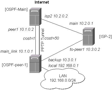
Let us assume that the link between the routers OSPF-Main and OSPF-peer-1 is the main one. When the main link goes down, the backup link should go through the ISP-2 router. Since we cannot control the ISP-2 router, we cannot run OSPF on the backup router like in the previous example with OSPF-peer-2. Therefore we have to create a tunnel between the routers OSPF-Main and OSPF-peer-1 that goes through the ISP-2 router. Thus, we will have two links between the routers, and the traffic should switch over to the backup when the main link goes down.
For this:
- We create a PPTP tunnel between our two routers, which goes over the ISP-2 router. Please consult the PPTP Interface Manual on how to create PPTP tunnels.
- Only the OSPF-Main router will have the default route configured. Its interfaces peer1 and pptp-in1 will be configured for the OSPF protocol. The interface main_gw will not be used for distributing the OSPF routing information.
- The router OSPF-peer-1 will distribute its connected and static route information, and receive the default route from OSPF-main using the OSPF protocol.
OSPF_Main Router Setup
The PPTP static server configuration is as follows:
[admin@OSPF-Main] > ip route add dst-address=10.3.0.1/32 gateway=10.2.0.1
[admin@OSPF-Main] > ppp secret add name=ospf service=pptp password=asdf4 \
\... local-address=10.4.0.2 remote-address=10.4.0.1
[admin@OSPF-Main] > interface pptp-server add name=pptp-in1 user=ospf
[admin@OSPF-Main] > interface pptp-server server set enabled=yes
[admin@OSPF-Main] > interface pptp-server print
Flags: X - disabled, D - dynamic, R - running
  #     NAME                 USER         MTU   CLIENT-ADDRESS  UPTIME   ENC...
  0     pptp-in1             ospf
[admin@OSPF-Main] >
The IP address configuration of the [OSPF_Main] router is as follows:
[admin@OSPF-Main] > ip address print
Flags: X - disabled, I - invalid, D - dynamic
  #   ADDRESS            NETWORK         BROADCAST       INTERFACE
  0   10.0.0.214/24      10.0.0.0        10.0.0.255      main_gw
  1   10.2.0.2/24        10.2.0.0        10.2.0.255      isp2
  2   10.1.0.2/24        10.1.0.0        10.1.0.255      peer1
  3 D 10.4.0.2/32        10.4.0.1        0.0.0.0         pptp-in1
[admin@OSPF-Main] >
OSPF settings:
[admin@OSPF-Main] routing ospf> print
                 router-id: 0.0.0.0
        distribute-default: if-installed-as-type-1
    redistribute-connected: as-type-1
       redistribute-static: no
          redistribute-rip: no
          redistribute-bgp: no
            metric-default: 1
          metric-connected: 20
             metric-static: 20
                metric-rip: 20
                metric-bgp: 20
[admin@OSPF-Main] routing ospf> interface add interface=pptp-in1 cost=50
[admin@OSPF-Main] routing ospf> interface print
  0 interface=pmi cost=150 priority=1 authentication-key=""
    retransmit-interval=5s transmit-delay=1s hello-interval=10s
    dead-interval=40s

[admin@OSPF-Main] routing ospf> area print
Flags: X - disabled, I - invalid
  #   NAME                     AREA-ID         STUB DEFAULT-COST AUTHENTICATION
  0   backbone                 0.0.0.0                           none

[admin@OSPF-Main] routing ospf> network print
Flags: X - disabled, I - invalid
  #   NETWORK            AREA
  0   10.1.0.0/24        backbone
  1   10.4.0.1/32        backbone
[admin@OSPF-Main] routing ospf>
Note, that the OSPF is configured only for the peer1 and pptp-in1 interfaces. Since the pptp-in1 is a point-to-point interface, the network address has 32 bits.
OSPF-peer-1 Router Setup
The PPTP client configuration is as follows:
[admin@OSPF-peer-1] > ip route add dst-address=10.2.0.2/32 gateway=10.3.0.2
[admin@OSPF-peer-1] > interface pptp-client add name=pptp-out1 user=ospf \
\... connect-to=10.2.0.2 password=asdf4 mtu=1500 mru=1500
[admin@OSPF-peer-1] > interface pptp-client enable pptp-out1
[admin@OSPF-peer-1] > interface pptp-client print
Flags: X - disabled, R - running
  0  R name="pptp-out1" mtu=1500 mru=1500 connect-to=10.2.0.2 user="ospf"
       password="asdf4" profile=default add-default-route=no

[admin@OSPF-peer-1] > interface pptp-client monitor pptp-out1
      status: "connected"
      uptime: 39m46s
    encoding: "none"

[admin@OSPF-peer-1] >
The IP address configuration of the [OSPF-peer-1] router is as follows:
[admin@OSPF-peer-1] > ip address print
Flags: X - disabled, I - invalid, D - dynamic
  #   ADDRESS            NETWORK         BROADCAST       INTERFACE
  0   10.1.0.1/24        10.1.0.0        10.1.0.255      main_link
  1   10.3.0.1/24        10.3.0.0        10.3.0.255      backup
  2   192.168.0.1/24     192.168.0.0     192.168.0.255   local
  3 D 10.4.0.1/32        10.4.0.2        0.0.0.0         pptp-out1
[admin@OSPF-peer-1] >
OSPF settings:
[admin@OSPF-peer-1] routing ospf> print
                 router-id: 0.0.0.0
        distribute-default: never
    redistribute-connected: as-type-1
       redistribute-static: no
          redistribute-rip: no
          redistribute-bgp: no
            metric-default: 1
          metric-connected: 20
             metric-static: 20
                metric-rip: 20
                metric-bgp: 20
[admin@OSPF-peer-1] routing ospf> interface add interface=pptp-out1 cost=50
[admin@OSPF-peer-1] routing ospf> interface print
  0 interface=pptp-out1 cost=50 priority=1 authentication-key=""
    retransmit-interval=5s transmit-delay=1s hello-interval=10s
    dead-interval=40s

[admin@OSPF-peer-1] routing ospf> area print
Flags: X - disabled, I - invalid
  #   NAME                     AREA-ID         STUB DEFAULT-COST AUTHENTICATION
  0   backbone                 0.0.0.0                           none

[admin@OSPF-peer-1] routing ospf> network print
Flags: X - disabled, I - invalid
  #   NETWORK            AREA
  0   10.1.0.0/24        backbone
  1   10.4.0.2/32        backbone
[admin@OSPF-peer-1] routing ospf>
Routing Tables
After the PPTP tunnel and OSPF protocol between two routers has been set up as described above, and the links between them are operational, the routing tables of the two routers should look as follows:
[admin@OSPF-Main] > ip route print
Flags: X - disabled, I - invalid, D - dynamic, J - rejected,
C - connect, S - static, R - rip, O - ospf, B - bgp
    #    DST-ADDRESS        G GATEWAY         DISTANCE INTERFACE
    0  S 0.0.0.0/0          r 10.0.0.1        1        main_gw
    1  S 10.3.0.1/32        r 10.2.0.1        1        isp2
    2 DO 192.168.3.0/24     r 10.1.0.1        110      peer1
    3 DO 192.168.0.0/24     r 10.1.0.1        110      peer1
    4 DO 10.4.0.2/32        r 10.1.0.1        110      peer1
    5 DC 10.4.0.1/32        r 0.0.0.0         0        pptp-in1
    6 DO 10.3.0.0/24        r 10.1.0.1        110      peer1
    7 DC 10.2.0.0/24        r 0.0.0.0         0        isp2
    8 DO 10.2.0.2/32        r 10.1.0.1        110      peer1
    9 DC 10.1.0.0/24        r 0.0.0.0         0        peer1
   10 DC 10.0.0.0/24        r 0.0.0.0         0        main_gw
[admin@OSPF-Main] >

=============================================================================

[admin@OSPF-peer-1] > ip route print
Flags: X - disabled, I - invalid, D - dynamic, J - rejected,
C - connect, S - static, R - rip, O - ospf, B - bgp
    #    DST-ADDRESS        G GATEWAY         DISTANCE INTERFACE
    0  S 10.2.0.0/24        r 10.3.0.2        1        backup
    1  S 192.168.3.0/24     r 192.168.0.20    1        local
    2  S 10.2.0.2/32        r 10.3.0.2        1        backup
    3 DO 0.0.0.0/0          r 10.1.0.2        110      main_link
    4 DC 192.168.0.0/24     r 0.0.0.0         0        local
    5 DC 10.4.0.2/32        r 0.0.0.0         0        pptp-out1
    6 DO 10.4.0.1/32        r 10.1.0.2        110      main_link
    7 DC 10.3.0.0/24        r 0.0.0.0         0        backup
    8 DC 10.1.0.0/24        r 0.0.0.0         0        main_link
    9 DO 10.0.0.0/24        r 10.1.0.2        110      main_link
[admin@OSPF-peer-1] >
Functioning of the Backup
If the link between routers OSPF-Main and OSPF-peer-1 goes down, the OSPF routing changes as follows:
[admin@OSPF-Main] > ip route print
Flags: X - disabled, I - invalid, D - dynamic, J - rejected,
C - connect, S - static, R - rip, O - ospf, B - bgp
    #    DST-ADDRESS        G GATEWAY         DISTANCE INTERFACE
    0  S 0.0.0.0/0          r 10.0.0.1        1        main_gw
    1  S 10.3.0.1/32        r 10.2.0.1        1        isp2
    2 DO 192.168.3.0/24     r 10.4.0.1        110      pptp-in1
    3 DO 192.168.0.0/24     r 10.4.0.1        110      pptp-in1
    4 DO 10.4.0.2/32        r 10.4.0.1        110      pptp-in1
    5 DC 10.4.0.1/32        r 0.0.0.0         0        pptp-in1
    6 DO 10.3.0.0/24        r 10.4.0.1        110      pptp-in1
    7 DC 10.2.0.0/24        r 0.0.0.0         0        isp2
    8 DO 10.2.0.2/32        r 10.4.0.1        110      pptp-in1
    9 DC 10.1.0.0/24        r 0.0.0.0         0        peer1
   10 DC 10.0.0.0/24        r 0.0.0.0         0        main_gw
[admin@OSPF-Main] >

==========================================================

[admin@OSPF-peer-1] > ip route print
Flags: X - disabled, I - invalid, D - dynamic, J - rejected,
C - connect, S - static, R - rip, O - ospf, B - bgp
    #    DST-ADDRESS        G GATEWAY         DISTANCE INTERFACE
    0  S 10.2.0.0/24        r 10.3.0.2        1        backup
    1  S 192.168.3.0/24     r 192.168.0.20    1        local
    2  S 10.2.0.2/32        r 10.3.0.2        1        backup
    3 DO 0.0.0.0/0          r 10.4.0.2        110      pptp-out1
    4 DC 192.168.0.0/24     r 0.0.0.0         0        local
    5 DC 10.4.0.2/32        r 0.0.0.0         0        pptp-out1
    6 DO 10.4.0.1/32        r 10.4.0.2        110      pptp-out1
    7 DC 10.3.0.0/24        r 0.0.0.0         0        backup
    8 DC 10.1.0.0/24        r 0.0.0.0         0        main_link
    9 DO 10.0.0.0/24        r 10.4.0.2        110      pptp-out1
[admin@OSPF-peer-1] >
As we see, all routing goes through the PPTP tunnel now.
Additional Resources
Recommended readings for guidelines on building OSPF networks:- http://www.ietf.org/rfc/rfc2328.txt
- OSPF Design Guide, Cisco Systems
- Designing Large-Scale IP Internetworks, Cisco Systems
© Copyright 1999-2003, MikroTik