Document revision 1.0 (19-May-2003)
This document applies to the MikroTik RouterOS V2.7
The MikroTik RouterOS supports the following WaveLAN/ORiNOCO 2.4GHz 11Mbps Wireless Adapter hardware:
Packages required : wireless
License required : 2.4/5GHz Wireless Client
Home menu level : /interface wavelan
Standards and Technologies : IEEE802.11b (
IEEE802.11b)
Hardware usage : not significant
Submenu level : /interface wavelan
WaveLAN/ORiNOCO 2.4GHz 11Mbps Wireless cards operate in 2.4 GHz band providing connection speed up to 11 Mbit/s.
name (name; default: wavelanN) - assigned interface name
mtu (integer: 256..2296; default: 1500) - Maximum Transmit Unit
mac-address (read-only: MAC address) - MAC address of the card
frequency (2412MHz | 2422MHz | 2432MHz | 2442MHz | 2452MHz | 2462MHz | 2472MHz |
2417MHz | 2427MHz | 2437MHz | 2447MHz | 2457MHz | 2467MHz | 2484MHz; default: 2412MHz) - channel frequency
data-rate (11Mbit/s | 1Mbit/s | 2Mbit/s | 5.5Mbit/s | auto; default: 11Mbit/s) - data rate
mode (infrastructure | ad-hoc; default: ad-hoc) - operation mode of the card
ssid (text: 0..32 chars; default: "") - Service Set Identifier
client-name (text: 0..32 chars; default: "") - client name
key1 (text; default: "") - encryption key #1
key2 (text; default: "") - encryption key #2
key3 (text; default: "") - encryption key #3
key4 (text; default: "") - encryption key #4
tx-key (key1 | key2 | key3 | key4; default: key1) - transmit key
encryption (no | yes; default: no) - specifies whether to use the encryption
arp (enabled | disabled | reply-only | proxy-arp; default: enabled) - ARP setting
[admin@MikroTik] interface> print
Flags: X - disabled, D - dynamic, R - running
  #    NAME                 TYPE             MTU
  0  R Public               1500  ether
  1  R Local                1500  ether
  2 X  wavelan1             1500  wavelan
[MikroTik] interface> enable 2
[admin@MikroTik] interface> print
Flags: X - disabled, D - dynamic, R - running
  #    NAME                 TYPE             MTU
  0  R Public               1500  ether
  1  R Local                1500  ether
  2  R wavelan1             1500  wavelan
[admin@MikroTik] interface>
More configuration and statistics parameters can be found under the /interface wavelan menu:
[admin@MikroTik] interface> wavelan
[admin@MikroTik] interface wavelan> print
Flags: X - disabled, R - running
  0  R name=wavelan1 mtu=1500 mac-address=00:02:2D:07:D8:44 arp=enabled
       frequency=2412MHz data-rate=11Mbit/s mode=ad-hoc ssid="" client-name=""
       key1="" key2="" key3="" key4="" tx-key=key1 encryption=no

[admin@MikroTik] interface wavelan>
You can monitor the status of the wireless interface:
[admin@MikroTik] interface wavelan> moitor 0
             bssid: 44:44:44:44:44:44
         frequency: 2422MHz
         data-rate: 11Mbit/s
              ssid: tsunami
    signal-quality: 0
      signal-level: 0
             noise: 0

[admin@MikroTik] interface wavelan>
To set the wireless interface for working with an IEEE 802.11b access point (register to the AP), you should set the following parameters:
All other parameters can be left as default. To configure the wireless interface for registering to an AP with ssid "MT_w_AP", it is enough to change the argument value of ssid to "MT_w_AP":
[admin@MikroTik] interface wavelan> set 0 ssid MT_w_AP mode infrastructure
[admin@MikroTik] interface wavelan> monitor wavelan1
             bssid: 00:40:96:42:0C:9C
         frequency: 2437MHz
         data-rate: 11Mbit/s
              ssid: MT_w_AP
    signal-quality: 65
      signal-level: 228
             noise: 163

[admin@MikroTik] interface wavelan>
Two possible wireless network configurations are discussed in the following examples:
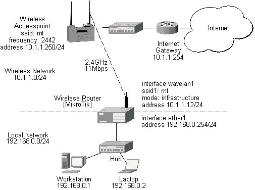
Let us consider the following network setup with WaveLAN / ORiNOCO or CISCO/Aironet Wireless Access Point or MikroTik router configured as Access Point as a base station and MikroTik Wireless Router as a client:
The access point is connected to the wired network's HUB and has IP address from the network 10.1.1.0/24. The minimum configuration required for the AP is:
The minimum configuration for the MikroTik router's wavelan wireless interface is:
[admin@MikroTik] interface wavelan> set wavelan1 ssid mt mode infrastructure
[admin@MikroTik] interface wavelan>
             bssid: 00:40:96:42:0C:9C
         frequency: 2437MHz
         data-rate: 11Mbit/s
              ssid: mt
    signal-quality: 64
      signal-level: 228
             noise: 163

[admin@MikroTik] interface wavelan>
The channel frequency argument does not have any meaning, since the frequency of the AP is used.
The IP addresses assigned to the wireless interface should be from the network 10.1.1.0/24, e.g.:
[admin@MikroTik] ip address> add address 10.1.1.12/24 interface wavelan1
[admin@MikroTik] ip address> add address 192.168.0.254/24 interface ether1
[admin@MikroTik] ip address> print
Flags: X - disabled, I - invalid, D - dynamic
  #   ADDRESS            NETWORK         BROADCAST       INTERFACE
  0   192.168.0.254/24   192.168.0.0     192.168.0.255   ether1
  1   10.1.1.12/24       10.1.1.0        10.1.1.255      wavelan1
[admin@MikroTik] ip address>
The default route should be set to the gateway router 10.1.1.254 (not the AP 10.1.1.250 !):
[admin@MikroTik] ip route> add gateway 10.1.1.254
[admin@MikroTik] > ip route print
Flags: X - disabled, I - invalid, D - dynamic, J - rejected,
C - connect, S - static, R - rip, O - ospf, B - bgp
    #    DST-ADDRESS        G GATEWAY         DISTANCE INTERFACE
    0  S 0.0.0.0/0          r 10.1.1.254      1        wavelan1
    1 DC 192.168.0.0/24     r 0.0.0.0         0        ether1
    2 DC 10.1.1.0/24        r 0.0.0.0         0        wavelan1
[admin@MikroTik] ip route>
Let us consider the following point-to-point wireless network setup with two MikroTik Wireless Routers:
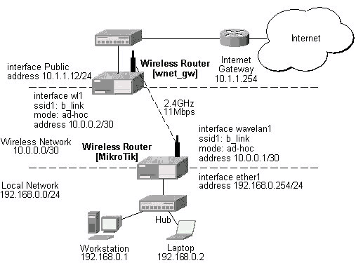
To establish a point-to-point link, the configuration of the wireless interface should be as follows:
The following command should be issued to change the settings for the wavelan interface:
[admin@MikroTik] interface wavelan> set 0 ssid b_link mode ad-hoc frewency 2412MHz
[admin@MikroTik] interface wavelan> monitor wavelan1
             bssid: 00:02:2D:07:17:23
         frequency: 2412MHz
         data-rate: 11Mbit/s
              ssid: b_link
    signal-quality: 0
      signal-level: 154
             noise: 154
[admin@MikroTik] interface wavelan>
The other router of the point-to-point link requires the same parameters to be set:
[admin@wnet_gw] interface wavelan> set 0 ssid b_link mode ad-hoc frequency 2412MHz
[admin@wnet_gw] interface wavelan> enable 0
[admin@wnet_gw] interface wavelan> monitor 0
             bssid: 00:02:2D:07:17:23
         frequency: 2412MHz
         data-rate: 11Mbit/s
              ssid: b_link
    signal-quality: 0
      signal-level: 154
             noise: 154
[admin@wnet_gw] interface wavelan>
As we see, the MAC address under the 'bssid' parameter is the same as generated on the first router.
If desired, IP addresses can be assigned to the wireless interfaces of the pint-to-point link routers using a smaller subnet, say 30-bit one:
[admin@MikroTik] ip address> add address 10.0.0.1/30 interface wavelan1
[admin@MikroTik] ip address> add address 192.168.0.254/24 interface ether1
[admin@MikroTik] ip address> print
  # ADDRESS         NETMASK         NETWORK         BROADCAST       INTERFACE
  0 10.0.0.1        255.255.255.252 10.0.0.1        10.0.0.3        wavelan1
  1 192.168.0.254   255.255.255.0   192.168.0.254   192.168.0.255   ether1
[admin@MikroTik] ip address> /ip route add gateway 10.0.0.2
[admin@MikroTik] > ip route print
Flags: X - disabled, I - invalid, D - dynamic, J - rejected,
C - connect, S - static, R - rip, O - ospf, B - bgp
    #    DST-ADDRESS        G GATEWAY         DISTANCE INTERFACE
    0  S 0.0.0.0/0          r 10.0.0.2        1        wavelan1
    1 DC 10.0.0.0/30        r 0.0.0.0         0        wavelan1
    2 DC 192.168.0.0/24     r 0.0.0.0         0        ether1
[admin@MikroTik] ip address>
The second router will have address 10.0.0.2, the default route to 10.1.1.254, and a static route for network 192.168.0.0/24 to 10.0.0.1:
[admin@wnet_gw] ip address> add address 10.0.0.2/30 interface wl1
[admin@wnet_gw] ip address> add address 10.1.1.12/24 interface Public
[admin@wnet_gw] ip address> print
  # ADDRESS         NETMASK         NETWORK         BROADCAST       INTERFACE
  0 10.0.0.2        255.255.255.252 10.0.0.2        10.0.0.3        wl1
  1 10.1.1.12       255.255.255.0   10.1.1.12       10.1.1.255      Public
[admin@wnet_gw] ip address> /ip route
[admin@wnet_gw] ip route> add gateway 10.1.1.254 interface Public
[admin@wnet_gw] ip route> add gateway 10.0.0.1 interface wl1 \
\... dst-address 192.168.0.0/24
[admin@MikroTik] > ip route print
Flags: X - disabled, I - invalid, D - dynamic, J - rejected,
C - connect, S - static, R - rip, O - ospf, B - bgp
    #    DST-ADDRESS        G GATEWAY         DISTANCE INTERFACE
    0 0.0.0.0/0             r 10.1.1.254      1        Public
    1 192.168.0.0/24        r 10.0.0.1        1        wl1
    2 10.0.0.0/30           r 0.0.0.0         0        wl1
    3 10.1.1.0/24           r 0.0.0.0         0        Public
[admin@wnet_gw] ip route>
The network connectivity can be tested by using ping:
[admin@MikroTik]> ping 10.0.0.2
10.0.0.2 pong: ttl=255 time=2 ms
10.0.0.2 pong: ttl=255 time=2 ms
10.0.0.2 pong: ttl=255 time=2 ms
3 packets transmitted, 3 packets received, 0% packet loss
round-trip min/avg/max = 2/2.0/2 ms
[admin@MikroTik]>
Let us consider the following point-to-point wireless network setup with one MikroTik Wireless Router and a laptop computer with Wavelan card:
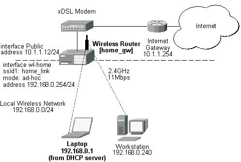
It is very important, that the MikroTik Router is configured prior turning on and configuring the wireless client. The MikroTik router should be up and running, so the client could join its network.
The configuration of the wireless interface of the MikroTik Router should be as follows:
The following command should be issued to change the settings for the wavelan interface:
[admin@home_gw] interface wavelan> set wl-home frequency 2447MHz \
/... mode ad-hoc ssid home_link
[admin@home_gw] interface wavelan> enable wl-home
[admin@home_gw] interface wavelan> print
[admin@MikroTik] interface wavelan> print
Flags: X - disabled, R - running
  0  R name=wl-home mtu=1500 mac-address=00:02:2D:07:D8:44 arp=enabled
       frequency=2447MHz data-rate=11Mbit/s mode=ad-hoc ssid="home_link"
       client-name="" key1="" key2="" key3="" key4="" tx-key=key1 encryption=no

[admin@home_gw] interface wavelan> monitor 0
             bssid: 02:02:2D:07:D8:44
         frequency: 2447MHz
         data-rate: 11Mbit/s
              ssid: home_link
    signal-quality: 0
      signal-level: 154
             noise: 154
[admin@home_gw] interface wavelan>
Configure the laptop computer with the Wavelan card following the manufacturer's instructions.
Note! In Ad-Hoc (Peer-to-Peer) mode the V1.76 ORiNOCO Client Manager program allows setting only the Network Name (ssid) parameter. The channel (frequency) parameter is chosen that of the other peer. Therefore, the MikroTik Router should be configured for the ad-hoc mode operation prior turning on the laptop Wavelan client.
If the laptop Wavelan client has established the wireless link with the MikroTik router, it should report the same parameters as set on the MikroTik router's wavelan interface:
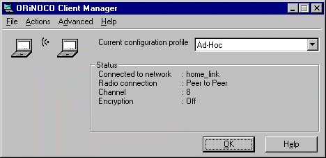
Here, we see the channel #8, which has 2447MHz frequency.
The IP addresses assigned to the wireless interface of the MikroTik Router should be from the network 192.168.0.0/24:
[admin@home_gw] ip address> add interface Public address 10.1.1.12/24
[admin@home_gw] ip address> add interface wl-home address 192.168.0.254/24
[admin@home_gw] ip address> print
  # ADDRESS         NETMASK         NETWORK         BROADCAST       INTERFACE
  0 10.1.1.12       255.255.255.0   10.1.1.12       10.1.1.255      Public
  1 192.168.0.254   255.255.255.0   192.168.0.254   192.168.0.255   wl-home
[admin@home_gw] ip address> /ip route
[admin@home_gw] ip route> add gateway 10.1.1.254
[admin#home_gw] ip route> print
[admin@MikroTik] > ip route print
Flags: X - disabled, I - invalid, D - dynamic, J - rejected,
C - connect, S - static, R - rip, O - ospf, B - bgp
    #    DST-ADDRESS        G GATEWAY         DISTANCE INTERFACE
    0  S 0.0.0.0/0          r 10.1.1.254      1        Public
    1 DC 192.168.0.0/24     r 0.0.0.0         0        wl-home
    2 DC 10.1.1.0/24        r 0.0.0.0         0        Public
[admin@MikroTik] ip route>
Use the ping command to test the connectivity from the router:
[admin@home_gw] > ping 192.168.0.1
192.168.0.1 pong: ttl=32 time=3 ms
192.168.0.1 pong: ttl=32 time=2 ms
192.168.0.1 pong: ttl=32 time=2 ms
3 packets transmitted, 3 packets received, 0% packet loss
round-trip min/avg/max = 2/2.3/3 ms
[admin@home_gw] >
For more information about the WaveLAN / ORiNOCO adapter hardware please see the relevant User’s Guides and Technical Reference Manuals in .pdf format from the manufacturer:
Information about configuring the ORiNOCO wireless access point can be found there: