encoding (string) - encryption and encoding (if asymmetric, separated with '/') being used in this connection
Example
Example of an established connection:
[admin@MikroTik] interface l2tp-client> monitor test2
      status: "connected"
      uptime: 4m27s
    encoding: "MPPE128 stateless"
[admin@MikroTik] interface l2tp-client>
L2TP Server Setup
Submenu level : /interface l2tp-server server
[admin@MikroTik] interface l2tp-server server> print
            enabled: no
                mtu: 1460
                mru: 1460
     authentication: mschap2
    default-profile: default
[admin@MikroTik] interface l2tp-server server>
Description
The L2TP server supports unlimited connections from clients. For each current connection, a dynamic interface is created.Property Description
enabled (yes | no; default: no) - defines whether L2TP server is enabled or notmtu (integer; default: 1460) - Maximum Transmit Unit. The optimal value is the MTU of the interface the tunnel is working over decreased by 40 (so, for 1500-byte ethernet link, set the MTU to 1460 to avoid fragmentation of packets)
mru (integer; default: 1460) - Maximum Receive Unit. The optimal value is the MTU of the interface the tunnel is working over decreased by 40 (so, for 1500-byte ethernet link, set the MTU to 1460 to avoid fragmentation of packets)
authentication (multiple choice: pap | chap | mschap1 | mschap2; default: mschap2) - authentication algorithm
default-profile - default profile to use
Example
To enable L2TP server:
[admin@MikroTik] interface l2tp-server server> set enabled=yes
[admin@MikroTik] interface l2tp-server server> print
            enabled: yes
                mtu: 1460
                mru: 1460
     authentication: mschap2
    default-profile: default
[admin@MikroTik] interface l2tp-server server>
L2TP Server Users
Submenu level : /interface l2tp-serverDescription
There are two types of items in L2TP server configuration - static users and dynamic connections. A dynamic connection can be established if the user database or the default-profile has its local-address and remote-address set correctly. When static users are added, the default profile may be left with its default values and only P2P user (in /ppp secret) should be configured. Note that in both cases P2P users must be configured properly.Property Description
name - interface nameuser - the name of the user that is configured statically or added dynamically
Statistics:
mtu - shows (cannot be set here) client's MTU
client-address - shows (cannot be set here) the IP of the connected client
uptime - shows how long the client is connected
encoding (string) - encryption and encoding (if asymmetric,
separated with '/') being used in this connection
Example
To add a static entry for ex1 user:[admin@MikroTik] interface l2tp-server> add user=ex1 [admin@MikroTik] interface l2tp-server> print Flags: X - disabled, D - dynamic, R - running # NAME USER MTU CLIENT-ADDRESS UPTIME ENC... 0 DR <l2tp-ex> ex 1460 10.0.0.202 6m32s none 1 l2tp-in1 ex1 [admin@MikroTik] interface l2tp-server>In this example an already connected user ex is shown besides the one we just added.
L2TP Router-to-Router Secure Tunnel Example
The following is an example of connecting two Intranets using an encrypted L2TP tunnel over the Internet.
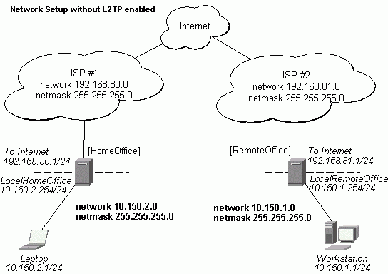
There are two routers in this example:
- [HomeOffice]
Interface LocalHomeOffice 10.150.2.254/24
Interface ToInternet 192.168.80.1/24 - [RemoteOffice]
Interface ToInternet 192.168.81.1/24
Interface LocalRemoteOffice 10.150.1.254/24
On the L2TP server a user must be set up for the client:
[admin@HomeOffice] ppp secret> add name=ex service=l2tp password=lkjrht
local-address=10.0.103.1 remote-address=10.0.103.2
[admin@HomeOffice] ppp secret> print detail
Flags: X - disabled
  0   name="ex" service=l2tp caller-id="" password="lkjrht" profile=default
      local-address=10.0.103.1 remote-address=10.0.103.2 routes==""

[admin@HomeOffice] ppp secret>
Then the user should be added in the L2TP server list:
[admin@HomeOffice] interface l2tp-server> add user=ex
[admin@HomeOffice] interface l2tp-server> print
Flags: X - disabled, D - dynamic, R - running
  #     NAME                 USER         MTU   CLIENT-ADDRESS  UPTIME   ENC...
  0     l2tp-in1             ex
[admin@HomeOffice] interface l2tp-server>
And finally, the server must be enabled:
[admin@HomeOffice] interface l2tp-server server> set enabled=yes
[admin@HomeOffice] interface l2tp-server server> print
            enabled: yes
                mtu: 1460
                mru: 1460
     authentication: mschap2
    default-profile: default
[admin@HomeOffice] interface l2tp-server server>
Add a L2TP client to the RemoteOffice router:
[admin@RemoteOffice] interface l2tp-client> add connect-to=192.168.80.1 user=ex \
\... password=lkjrht disabled=no
[admin@RemoteOffice] interface l2tp-client> print
Flags: X - disabled, R - running
  0  R name="l2tp-out1" mtu=1460 mru=1460 connect-to=192.168.80.1 user="ex"
       password="lkjrht" profile=default add-default-route=no


[admin@RemoteOffice] interface l2tp-client>
Thus, a L2TP tunnel is created between the routers. This tunnel is like an Ethernet point-to-point connection between the routers with IP addresses 10.0.103.1 and 10.0.103.2 at each router. It enables 'direct' communication between the routers over third party networks.
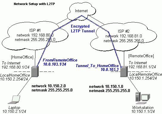
To route the local Intranets over the L2TP tunnel – add these routes:
[admin@HomeOffice] > ip route add dst-address 10.150.1.0/24 gateway 10.0.103.2
[admin@RemoteOffice] > ip route add dst-address 10.150.2.0/24 gateway 10.0.103.1
On the L2TP server it can alternatively be done using routes parameter of the user configuration:
[admin@HomeOffice] ppp secret> print detail
Flags: X - disabled
  0   name="ex" service=l2tp caller-id="" password="lkjrht" profile=default
      local-address=10.0.103.1 remote-address=10.0.103.2 routes==""

[admin@HomeOffice] ppp secret> set 0 routes="10.150.1.0/24 10.0.103.2 1"
[admin@HomeOffice] ppp secret> print detail
Flags: X - disabled
  0   name="ex" service=l2tp caller-id="" password="lkjrht" profile=default
      local-address=10.0.103.1 remote-address=10.0.103.2
      routes="10.150.1.0/24 10.0.103.2 1"

[admin@HomeOffice] ppp secret>
Test the L2TP tunnel connection:
[admin@RemoteOffice]> /ping 10.0.103.1
10.0.103.1 pong: ttl=255 time=3 ms
10.0.103.1 pong: ttl=255 time=3 ms
10.0.103.1 pong: ttl=255 time=3 ms
ping interrupted
3 packets transmitted, 3 packets received, 0% packet loss
round-trip min/avg/max = 3/3.0/3 ms
Test the connection through the L2TP tunnel to the LocalHomeOffice interface:
[admin@RemoteOffice]> /ping 10.150.2.254
10.150.2.254 pong: ttl=255 time=3 ms
10.150.2.254 pong: ttl=255 time=3 ms
10.150.2.254 pong: ttl=255 time=3 ms
ping interrupted
3 packets transmitted, 3 packets received, 0% packet loss
round-trip min/avg/max = 3/3.0/3 ms
To bridge a LAN over this secure tunnel, please see the example in the 'EoIP' section of the manual. To set the maximum speed for traffic over this tunnel, please consult the 'Queues' section.
Connecting a Remote Client via L2TP Tunnel
The following example shows how to connect a computer to a remote office network over L2TP encrypted tunnel giving that computer an IP address from the same network as the remote office has (without need of bridging over eoip tunnels)
Please, consult the respective manual on how to set up a L2TP client with the software You are using.
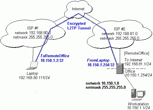
The router in this example:
- [RemoteOffice]
Interface ToInternet 192.168.81.1/24
Interface Office 10.150.1.254/24
On the L2TP server a user must be set up for the client:
[admin@RemoteOffice] ppp secret> add name=ex service=l2tp password=lkjrht
local-address=10.150.1.254 remote-address=10.150.1.2
[admin@RemoteOffice] ppp secret> print detail
Flags: X - disabled
  0   name="ex" service=l2tp caller-id="" password="lkjrht" profile=default
      local-address=10.150.1.254 remote-address=10.150.1.2 routes==""

[admin@RemoteOffice] ppp secret>
Then the user should be added in the L2TP server list:
[admin@RemoteOffice] interface l2tp-server> add name=FromLaptop user=ex
[admin@RemoteOffice] interface l2tp-server> print
Flags: X - disabled, D - dynamic, R - running
  #     NAME                 USER         MTU   CLIENT-ADDRESS  UPTIME   ENC...
  0     FromLaptop           ex
[admin@RemoteOffice] interface l2tp-server>
And the server must be enabled:
[admin@RemoteOffice] interface l2tp-server server> set enabled=yes
[admin@RemoteOffice] interface l2tp-server server> print
            enabled: yes
                mtu: 1460
                mru: 1460
     authentication: mschap2
    default-profile: default
[admin@RemoteOffice] interface l2tp-server server>
Finally, the proxy APR must be enabled on the 'Office' interface:
[admin@RemoteOffice] interface ethernet> set Office arp=proxy-arp
[admin@RemoteOffice] interface ethernet> print
Flags: X - disabled, R - running
  #    NAME                 MTU   MAC-ADDRESS       ARP
  0  R ToInternet           1500  00:30:4F:0B:7B:C1 enabled
  1  R Office               1500  00:30:4F:06:62:12 proxy-arp
[admin@RemoteOffice] interface ethernet>
L2TP Setup for Windows
Microsoft provides L2TP client support for Windows XP, 2000, NT4, ME and 98.
Windows 2000 and XP include support in the Windows setup or automatically install L2TP.
For 98, NT and ME, installation requires a download from Microsoft (L2TP/IPSec VPN Client)
For more information, see:
Microsoft L2TP/IPSec VPN Client
On Windows 2000, L2TP setup without IPsec requires editting registry:
Disabling IPSec for the Windows 2000 Client
Disabling IPSEC Policy Used with L2TP
Troubleshooting
- I use firewall and I cannot establish L2TP connection
Make sure UDP connections can pass through both directions between your sites. - My Windows L2TP/IPSec VPN Client fails to connect to L2TP server with "Error 789"
or "Error 781"
The error messages 789 and 781 occur when IPsec is not configured properly on both ends. See the respective documentation on how to configure IPsec in the Microsoft L2TP/IPSec VPN Client and in the MikroTik RouterOS. If you do not want to use IPsec, it can be easily switched off on the client side.
Note: if you are using Windows 2000, you need to edit system registry using regedt32.exe or regedit.exe. Add the following registry value to HKEY_LOCAL_MACHINE\System\CurrentControlSet\Services\Rasman\Parameters:Value Name: ProhibitIpSec Data Type: REG_DWORD Value: 1
You must restart the Windows 2000 for the changes to take effectFor more information on configuring Windows 2000, see:
Configuring Cisco IOS and Windows 2000 Clients for L2TP Using Microsoft IAS
Disabling IPSEC Policy Used with L2TP
How to Configure a L2TP/IPSec Connection Using Pre-shared Key Authentication
© Copyright 1999-2003, MikroTik