OSPF distributes routing information between routers belonging to a single autonomous system (AS). An AS is a group of routers exchanging routing information via a common routing protocol.
When migrating from V2.4 to V2.5, please note that:
Installation
The OSPF feature is included in the “routing” package.
The package file routing-2.x.y.npk can be downloaded
from MikroTik’s web page www.mikrotik.com.
To install the package, please upload it to the router
with ftp and reboot. You may check to see if the routing package
is installed with the command:
[MikroTik] > system package print
  # NAME                   VERSION               BUILD-TIME           UNINSTALL
  0 routing                2.4.5                 dec/04/2001 14:54:29 no
  1 snmp                   2.4.5                 dec/04/2001 14:54:41 no
  2 ppp                    2.4.5                 dec/04/2001 14:55:36 no
  3 pppoe                  2.4.5                 dec/04/2001 14:56:30 no
  4 ssh                    2.4.5                 dec/04/2001 14:58:22 no
  5 pptp                   2.4.5                 dec/04/2001 14:55:54 no
  6 cyclades               2.4.5                 dec/04/2001 14:58:39 no
  7 framerelay             2.4.5                 dec/04/2001 15:07:21 no
  8 system                 2.4.5                 dec/04/2001 14:53:19 no
[MikroTik] >
Hardware Resource Usage
There is no significant resource usage.
OSPF Description
For OSPF description and implementation guidelines please refer to list of Additional Resources.
Current document discusses OSPF configuration for MikroTik RouterOS.
When implementing the OSPF, all routers should be configured in a coordinated manner.
Routers belonging to one area should have the same area ID configured.
OSPF Setup
The OSPF management can be accessed under the /routing ospf submenu.
After you have determined which routers belong to your OSPF area, you have to configure the following settings on each of the routers belonging to the selected area:
Note! The OSPF protocol is started only on interfaces configured under the /routing ospf network
[MikroTik] routing ospf> print
                 router-id: 0.0.0.0
        distribute-default: never
    redistribute-connected: no
       redistribute-static: no
          redistribute-rip: no
[MikroTik] routing ospf>
[MikroTik] routing ospf> set redistribute-static=yes redistribute-connected=yes
Argument description:
router-id – The Router ID. If not specified (default 0.0.0.0), OSPF uses the largest IP address configured on the interfaces as its router ID.
redistribute-connected – ( yes / no ) If set to yes, then the router will redistribute the information about all connected routes, i.e., routes to networks, that can be directly reached from the router.
redistribute-static – ( yes / no ) If set to yes, then the router will redistribute the information about all static routes added to its routing database, i.e., routes, that have been created using the /ip route add command of the router.
redistribute-rip – ( yes / no ) If set to yes, then the router will redistribute the information about all routes learned by the RIP protocol.
distribute-default – ( always / if-installed / never ). Controls how to propagate the default route to other routers.
never - do not send own default route to other routers;
if-installed - send the default route only if it has been installed (a static default route, or route added by DHCP, PPP, etc.);
always - always send the default route.
Note! Within an area, only the area gateway (border) router should have the propagation of the default route enabled.
Usually you want to redistribute connected and static routes, if any. Therefore change the settings for these arguments and proceed to the OSPF areas and networks.
[MikroTik] routing ospf area> print detail
Flags: X - disabled
  0 name=backbone area-id=0.0.0.0 stub-area=no default-cost=0
    authentication=none

[MikroTik] routing ospf area>
To define additional OSPF area(s) for the router, use the /routing ospf area add command:
[MikroTik] routing ospf area> add area-id=0.0.10.5 name=local_10
[MikroTik] routing ospf area> print
Flags: X - disabled
  0 name=backbone area-id=0.0.0.0 stub-area=no default-cost=0
    authentication=none

  1 name=local_10 area-id=0.0.10.5 stub-area=no default-cost=0
    authentication=none

[MikroTik] routing ospf area>
Argument description:
name - area name. Cannot be changed for the backbone area.
area-id - area ID, must be in IP address notation. Cannot be changed for the backbone area.
default-cost - Cost for the default summary route used for a stub area. Only for area boundary router.
stub - ( yes / no ) Sets the area type.
authentication - ( md5 / none / simple ) authentication method for OSPF
none - no authentication;
simple - clear text authentication;
md5 - Keyed Message Digest 5 (MD5) authentication.
To start the OSPF protocol, you have to define the interfaces on which OSPF runs and the area ID for those interfaces. Use the /routing ospf network add command:
[MikroTik] routing ospf network> add area=local_10 network=10.0.0.0/24
[MikroTik] routing ospf network> print
Flags: X - disabled
  #   NETWORK            AREA
  0   10.0.0.0/24        local_10
[MikroTik] routing ospf network>
Argument description:
area - Area to be associated with the address range. The area name should be from the /routing ospf area list.
network - the network address/mask that is associated with the area. The network argument allows defining one or multiple interfaces to be associated with a specific OSPF area. Only local address of the router should be covered by the network address/mask.
Note on using OSPF over point-to-point links:
Never include the remote address of a pint-to-point link (PPP, PPPoE, PPTP, IPIP)
in to the network address/mask! OSPF will not function properly.
Only the local address should be included! See the Application example below!
For OSPF to operate on the interface, any address of that interface must be covered by the network address specified in the network record. For example:
[MikroTik] routing ospf network> /ip address print
Flags: X - disabled, I - invalid, D - dynamic
  #   ADDRESS            NETWORK         BROADCAST       INTERFACE
  0   10.0.0.212/24      10.0.0.212      10.0.0.255      ether1
  1   192.168.0.1/24     192.168.0.0     192.168.0.255   ether1
  2   1.1.1.1/24         1.1.1.0         1.1.1.255       sync1
[MikroTik] routing ospf network> print
Flags: X - disabled
  #   NETWORK            AREA
  0   192.168.0.0/24     local_10
[MikroTik] routing ospf network> /ip route print
Flags: X - disabled, I - invalid, D - dynamic, R - rejected
  #    TYPE    DST-ADDRESS        NEXTHOP-S... GATEWAY     DISTANCE INTERFACE
  0    static  0.0.0.0/0          A            10.0.0.1    1        ether1
  1 I  ospf    192.168.0.0/24     A            0.0.0.0     110      ether1
  2 D  connect 192.168.0.0/24     A            0.0.0.0     0        ether1
  3 I  ospf    10.0.0.0/24        A            0.0.0.0     110      ether1
  4 D  connect 10.0.0.0/24        A            0.0.0.0     0        ether1
  5 D  connect 1.1.1.0/24         A            0.0.0.0     0        sync1
[MikroTik] routing ospf network>
The items #1 and #3 show, that OSPF protocol is running on the interface ether1, and two routes have been installed by the routing daemon. The routes are marked as invalid, because these routes match the connected routes, but there should not be two routes to the same destination. This is no malfunctioning of the program.
Normally you do not need to make any changes for the ospf interfaces, unless you want to adjust some interval settings for the OSPF messages, or change the interface cost or priority. To change the OSPF interface settings, go to the /routing ospf interface menu:
[MikroTik] routing ospf interface> set sync1 cost=50
[MikroTik] routing ospf interface> print
Flags: X - disabled
  0   interface=ether1 cost=1 priority=1 authentication-key=""
      dead-interval=40s hello-interval=10s retransmit-interval=5s
      transmit-delay=1s

  1   interface=sync1 cost=50 priority=1 authentication-key=""
      dead-interval=40s hello-interval=10s retransmit-interval=5s
      transmit-delay=1s

[MikroTik] routing ospf interface>
Argument description:
authentication-key - Authentication key to be used by neighboring routers that are using OSPF's simple password authentication
cost - Interface cost (1..65535) expressed as the link state metric.
dead-interval - Interval after which a neighbor is declared dead. The interval is advertised in the router's hello packets. This value must be the same for all routers and access servers on a specific network.
hello-interval - The interval between hello packets that the router sends on the interface. The smaller the hello interval, the faster topological changes will be detected, but more routing traffic will ensue. This value must be the same for all routers on a specific network.
priority - Router priority (0..255). It helps determine the designated router for the network. When two routers attached to a network both attempt to become the designated router, the one with the higher router priority takes precedence.
retransmit-interval - Time between retransmitting lost link state advertisements (3..65535 seconds). When a router sends a link state advertisement (LSA) to its neighbor, it keeps the LSA until it receives back the acknowledgment. If it receives no acknowledgment in seconds, it will retransmit the LSA.
transmit-delay - Link state transmit delay (1..65535 seconds) is the estimated time it takes to transmit a link state update packet on the interface
[MikroTik] routing ospf network> print
Flags: X - disabled
  #   NETWORK            AREA
  0   192.168.0.0/24     local_10
[MikroTik] routing ospf network> disable 0; enable 0
[MikroTik] routing ospf network>
To avoid such situations, there should always be a static route to the IP address of the PPTP peer. Please consult the PPTP Interface Manual for more information on it.
[MikroTik] ip address> print
Flags: X - disabled, I - invalid, D - dynamic
  #   ADDRESS            NETWORK         BROADCAST       INTERFACE
  0   10.7.1.3/24        10.7.1.0        10.7.1.255      backbone
  1   192.168.223.55/25  192.168.223.0   192.168.223.127 aironet
  2 D 10.2.0.7/32        10.2.0.8        0.0.0.0         pptp-out1
[MikroTik] ip address>
Use '/router ospf network add network=10.2.0.8/32 area=backbone'.
Additional Resources
Recommended readings for guidelines on building OSPF networks:
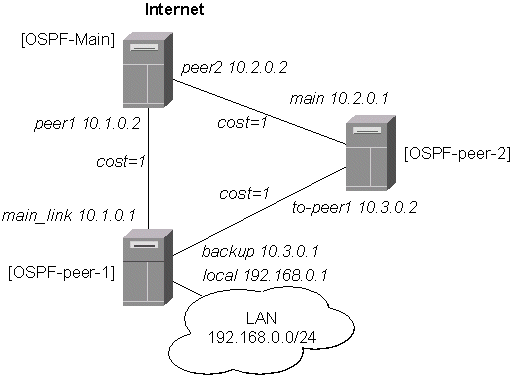
Let us consider the following examples of OSPF protocol used for backup links:
OSPF Backup without using Tunnel
This examples shows how to use OSPF for backup purposes, if you are controlling all the involved routers, and you can run OSPF on them.
Let us assume, that the link between the routers OSPF-Main and OSPF-peer-1 is the main one. If it goes down, we want the traffic switch over to the links going through the router OSPF-peer-2.
For this:
The IP address configuration of the [OSPF_Main] router is as follows:
[OSPF-Main] interface> /ip address print
Flags: X - disabled, I - invalid, D - dynamic
  #   ADDRESS            NETWORK         BROADCAST       INTERFACE
  0   10.0.0.214/24      10.0.0.0        10.0.0.255      main_gw
  1   10.1.0.2/24        10.1.0.0        10.1.0.255      peer1
  2   10.2.0.2/24        10.2.0.0        10.2.0.255      peer2
[OSPF-Main] interface>
OSPF settings:
[OSPF-Main] > routing ospf print
                 router-id: 0.0.0.0
    redistribute-connected: yes
       redistribute-static: yes
          redistribute-rip: no
        distribute-default: if-installed
[OSPF-Main] > routing ospf area print
Flags: X - disabled
  0   name=backbone area-id=0.0.0.0 default-cost=0 stub=no
      authentication=none

  1   name=local_10 area-id=0.0.0.1 default-cost=0 stub=no
      authentication=none

[OSPF-Main] > routing ospf network print
Flags: X - disabled
  #   NETWORK            AREA
  0   10.1.0.0/24        local_10
  1   10.2.0.0/24        local_10
[OSPF-Main] >
The IP address configuration of the [OSPF-peer-1] router is as follows:
[OSPF-peer-1] > ip address print
Flags: X - disabled, I - invalid, D - dynamic
  #   ADDRESS            NETWORK         BROADCAST       INTERFACE
  0   10.1.0.1/24        10.1.0.0        10.1.0.255      main_link
  1   10.3.0.1/24        10.3.0.0        10.3.0.255      backup
  2   192.168.0.1/24     192.168.0.0     192.168.0.255   local
[OSPF-peer-1] >
OSPF settings:
[OSPF-peer-1] > routing ospf print
                 router-id: 0.0.0.0
    redistribute-connected: yes
       redistribute-static: yes
          redistribute-rip: no
        distribute-default: never
[OSPF-peer-1] > routing ospf area print
Flags: X - disabled
  0   name=backbone area-id=0.0.0.0 default-cost=0 stub=no
      authentication=none

  1   name=local_10 area-id=0.0.0.1 default-cost=0 stub=no
      authentication=none

[OSPF-peer-1] > routing ospf network print
Flags: X - disabled
  #   NETWORK            AREA
  0   10.3.0.0/24        local_10
  1   10.1.0.0/24        local_10
[OSPF-peer-1] >
The IP address configuration of the [OSPF-peer-2] router is as follows:
[OSPF-peer-2] > ip address print
Flags: X - disabled, I - invalid, D - dynamic
  #   ADDRESS            NETWORK         BROADCAST       INTERFACE
  0   10.2.0.1/24        10.2.0.0        10.2.0.255      main
  1   10.3.0.2/24        10.3.0.0        10.3.0.255      to-peer2
[OSPF-peer-2] >
OSPF settings:
[OSPF-peer-2] > routing ospf print
                 router-id: 0.0.0.0
    redistribute-connected: yes
       redistribute-static: yes
          redistribute-rip: no
        distribute-default: never
[OSPF-peer-2] > routing ospf area print
Flags: X - disabled
  0   name=backbone area-id=0.0.0.0 default-cost=0 stub=no
      authentication=none

  1   name=local_10 area-id=0.0.0.1 default-cost=0 stub=no
      authentication=none

[OSPF-peer-2] > routing ospf network print
Flags: X - disabled
  #   NETWORK            AREA
  0   10.2.0.0/24        local_10
  1   10.3.0.0/24        local_10
[OSPF-peer-2] >
After the three routers have been set up as described above, and the links between them are operational, the routing tables of the three routers should look as follows:
[OSPF-Main] > ip route print
Flags: X - disabled, I - invalid, D - dynamic, R - rejected
  #    TYPE    DST-ADDRESS        NEXTHOP-S... GATEWAY     DISTANCE INTERFACE
  0    static  0.0.0.0/0          A            10.0.0.1    1        main_gw
  1 D  ospf    192.168.3.0/24     A            10.1.0.1    110      peer1
  2 D  ospf    192.168.0.0/24     A            10.1.0.1    110      peer1
  3 D  ospf    10.3.0.0/24        A            10.2.0.1    110      peer2
                                  A            10.1.0.1             peer1
  4 I  ospf    10.2.0.0/24        A            0.0.0.0     110      peer2
  5 D  connect 10.2.0.0/24        A            0.0.0.0     0        peer2
  6 I  ospf    10.1.0.0/24        A            0.0.0.0     110      peer1
  7 D  connect 10.1.0.0/24        A            0.0.0.0     0        peer1
  8 D  connect 10.0.0.0/24        A            0.0.0.0     0        main_gw
[OSPF-Main] >
=============================================================================
[OSPF-peer-1] > ip route print
Flags: X - disabled, I - invalid, D - dynamic, R - rejected
  #    TYPE    DST-ADDRESS        NEXTHOP-S... GATEWAY     DISTANCE INTERFACE
  0    static  192.168.3.0/24     A            192.168.0.3 1        local
  1 D  ospf    0.0.0.0/0          A            10.1.0.2    110      main_link
  2 D  connect 192.168.0.0/24     A            0.0.0.0     0        local
  3 I  ospf    10.3.0.0/24        A            0.0.0.0     110      backup
  4 D  connect 10.3.0.0/24        A            0.0.0.0     0        backup
  5 D  ospf    10.2.0.0/24        A            10.1.0.2    110      main_link
                                  A            10.3.0.2             backup
  6 I  ospf    10.1.0.0/24        A            0.0.0.0     110      main_link
  7 D  connect 10.1.0.0/24        A            0.0.0.0     0        main_link
  8 D  ospf    10.0.0.0/24        A            10.1.0.2    110      main_link
[OSPF-peer-1] >
=============================================================================
[OSPF-peer-2] > ip route print
Flags: X - disabled, I - invalid, D - dynamic, R - rejected
  #    TYPE    DST-ADDRESS        NEXTHOP-S... GATEWAY     DISTANCE INTERFACE
  0 D  ospf    0.0.0.0/0          A            10.2.0.2    110      main
  1 D  ospf    192.168.3.0/24     A            10.3.0.1    110      to-peer2
  2 D  ospf    192.168.0.0/24     A            10.3.0.1    110      to-peer2
  3 I  ospf    10.3.0.0/24        A            0.0.0.0     110      to-peer2
  4 D  connect 10.3.0.0/24        A            0.0.0.0     0        to-peer2
  5 I  ospf    10.2.0.0/24        A            0.0.0.0     110      main
  6 D  connect 10.2.0.0/24        A            0.0.0.0     0        main
  7 D  ospf    10.1.0.0/24        A            10.3.0.1    110      to-peer2
                                  A            10.2.0.2             main
  8 D  ospf    10.0.0.0/24        A            10.2.0.2    110      main
[OSPF-peer-2] >
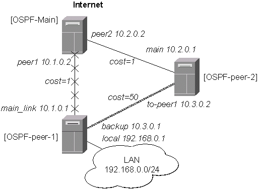
Please note the three equal cost multipath routes (multiple gateways for one destination) in this setup. They have been created by the OSPF, because there is equal cost to go, for example, from the router OSPF-peer-2 to the network 10.1.0.0/24.
The cost is calculated as the sum of costs over each hop to the destination. Unless this is not specially desired, we may want to avoid such situations, i.e., and adjust the cost settings for the interfaces (links) accordingly.
Lat as assume, that the link between the routers OSPF-peer-1 and OSPF-peer-2 has a higher cost (might be slower, we have to pay more for the traffic through it, etc.). Since we have left all ospf interface cost settings as default (cost=1), we need to change the following settings:
[OSPF-peer-1] > routing ospf interface set backup cost=50
[OSPF-peer-2] > routing ospf interface set to-peer2 cost=50
The revised network diagram:

After changing the cost settings, we have only one equal cost multipath route left - to the network 10.3.0.0/24 from the OSPF-Main router:
[OSPF-Main] > ip route print
Flags: X - disabled, I - invalid, D - dynamic, R - rejected
  #    TYPE    DST-ADDRESS        NEXTHOP-S... GATEWAY     DISTANCE INTERFACE
  0    static  0.0.0.0/0          A            10.0.0.1    1        main_gw
  1 D  ospf    192.168.3.0/24     A            10.1.0.1    110      peer1
  2 D  ospf    192.168.0.0/24     A            10.1.0.1    110      peer1
  3 D  ospf    10.3.0.0/24        A            10.2.0.1    110      peer2
                                  A            10.1.0.1             peer1
  4 I  ospf    10.2.0.0/24        A            0.0.0.0     110      peer2
  5 D  connect 10.2.0.0/24        A            0.0.0.0     0        peer2
  6 I  ospf    10.1.0.0/24        A            0.0.0.0     110      peer1
  7 D  connect 10.1.0.0/24        A            0.0.0.0     0        peer1
  8 D  connect 10.0.0.0/24        A            0.0.0.0     0        main_gw
[OSPF-Main] >
===========================================================
[OSPF-peer-1] > ip route print
Flags: X - disabled, I - invalid, D - dynamic, R - rejected
  #    TYPE    DST-ADDRESS        NEXTHOP-S... GATEWAY     DISTANCE INTERFACE
  0    static  192.168.3.0/24     A            192.168.0.3 1        local
  1 D  ospf    0.0.0.0/0          A            10.1.0.2    110      main_link
  2 D  connect 192.168.0.0/24     A            0.0.0.0     0        local
  3 I  ospf    10.3.0.0/24        A            0.0.0.0     110      backup
  4 D  connect 10.3.0.0/24        A            0.0.0.0     0        backup
  5 D  ospf    10.2.0.0/24        A            10.1.0.2    110      main_link
  6 I  ospf    10.1.0.0/24        A            0.0.0.0     110      main_link
  7 D  connect 10.1.0.0/24        A            0.0.0.0     0        main_link
  8 D  ospf    10.0.0.0/24        A            10.1.0.2    110      main_link
[OSPF-peer-1] >
===========================================================
[OSPF-peer-2] > ip route print
Flags: X - disabled, I - invalid, D - dynamic, R - rejected
  #    TYPE    DST-ADDRESS        NEXTHOP-S... GATEWAY     DISTANCE INTERFACE
  0 D  ospf    0.0.0.0/0          A            10.2.0.2    110      main
  1 D  ospf    192.168.3.0/24     A            10.2.0.2    110      main
  2 D  ospf    192.168.0.0/24     A            10.2.0.2    110      main
  3 I  ospf    10.3.0.0/24        A            0.0.0.0     110      to-peer2
  4 D  connect 10.3.0.0/24        A            0.0.0.0     0        to-peer2
  5 I  ospf    10.2.0.0/24        A            0.0.0.0     110      main
  6 D  connect 10.2.0.0/24        A            0.0.0.0     0        main
  7 D  ospf    10.1.0.0/24        A            10.2.0.2    110      main
  8 D  ospf    10.0.0.0/24        A            10.2.0.2    110      main
[OSPF-peer-2] >
If the link between routers OSPF-Main and OSPF-peer-1 goes down, we have the following situation:
The OSPF routing changes as follows:
[OSPF-Main] > ip route print
Flags: X - disabled, I - invalid, D - dynamic, R - rejected
  #    TYPE    DST-ADDRESS        NEXTHOP-S... GATEWAY     DISTANCE INTERFACE
  0    static  0.0.0.0/0          A            10.0.0.1    1        main_gw
  1 D  ospf    192.168.3.0/24     A            10.2.0.1    110      peer2
  2 D  ospf    192.168.0.0/24     A            10.2.0.1    110      peer2
  3 D  ospf    10.3.0.0/24        A            10.2.0.1    110      peer2
  4 I  ospf    10.2.0.0/24        A            0.0.0.0     110      peer2
  5 D  connect 10.2.0.0/24        A            0.0.0.0     0        peer2
  6 I  ospf    10.1.0.0/24        A            0.0.0.0     110      peer1
  7 D  connect 10.1.0.0/24        A            0.0.0.0     0        peer1
  8 D  connect 10.0.0.0/24        A            0.0.0.0     0        main_gw
[OSPF-Main] >
==========================================================
[OSPF-peer-1] > ip route print
Flags: X - disabled, I - invalid, D - dynamic, R - rejected
  #    TYPE    DST-ADDRESS        NEXTHOP-S... GATEWAY     DISTANCE INTERFACE
  0    static  192.168.3.0/24     A            192.168.0.3 1        local
  1 D  ospf    0.0.0.0/0          A            10.3.0.2    110      backup
  2 D  connect 192.168.0.0/24     A            0.0.0.0     0        local
  3 I  ospf    10.3.0.0/24        A            0.0.0.0     110      backup
  4 D  connect 10.3.0.0/24        A            0.0.0.0     0        backup
  5 D  ospf    10.2.0.0/24        A            10.3.0.2    110      backup
  6 I  ospf    10.1.0.0/24        A            0.0.0.0     110      main_link
  7 D  connect 10.1.0.0/24        A            0.0.0.0     0        main_link
  8 D  ospf    10.0.0.0/24        A            10.3.0.2    110      backup
[OSPF-peer-1] >
==========================================================
[OSPF-peer-2] > ip route print
Flags: X - disabled, I - invalid, D - dynamic, R - rejected
  #    TYPE    DST-ADDRESS        NEXTHOP-S... GATEWAY     DISTANCE INTERFACE
  0 D  ospf    0.0.0.0/0          A            10.2.0.2    110      main
  1 D  ospf    192.168.3.0/24     A            10.3.0.1    110      to-peer2
  2 D  ospf    192.168.0.0/24     A            10.3.0.1    110      to-peer2
  3 I  ospf    10.3.0.0/24        A            0.0.0.0     110      to-peer2
  4 D  connect 10.3.0.0/24        A            0.0.0.0     0        to-peer2
  5 I  ospf    10.2.0.0/24        A            0.0.0.0     110      main
  6 D  connect 10.2.0.0/24        A            0.0.0.0     0        main
  7 D  ospf    10.1.0.0/24        A            10.2.0.2    110      main
  8 D  ospf    10.0.0.0/24        A            10.2.0.2    110      main
[OSPF-peer-2] >
The change of the routing takes approximately 40 seconds (the hello-interval setting). If required, this setting can be adjusted, but it should be done on all routers within the OSPF area!
OSPF Backup using Encrypted Tunnel through a Third Party
(This example is based on V2.5 of the MikroTik RouterOS, which is very similar to V2.4)
This example shows how to use OSPF for backup purposes, if you have to use third party link for backup, and you are not controlling the routers on the backup link.
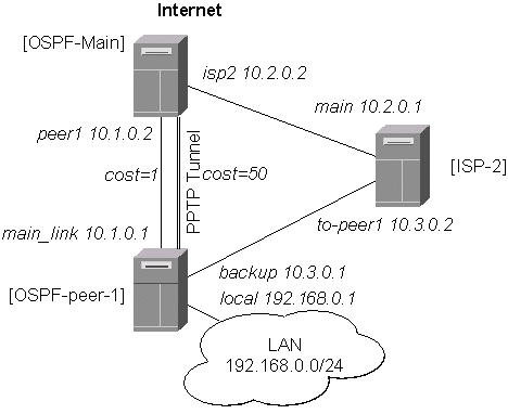
Let us assume that the link between the routers OSPF-Main and OSPF-peer-1 is the main one. When the main link goes down, the backup link should go through the ISP-2 router. Since we cannot control the ISP-2 router, we cannot run OSPF on the backup router like in the previous example with OSPF-peer-2. Therefore we have to create a tunnel between the routers OSPF-Main and OSPF-peer-1 that goes through the ISP-2 router. Thus, we will have two links between the routers, and the traffic should switch over to the backup when the main link goes down.
For this:
The PPTP static server configuration is as follows:
[OSPF-Main] > ip route add dst-address=10.3.0.1/32 gateway=10.2.0.1
[OSPF-Main] > user add name=ospf group=ppp password=asdf4
[OSPF-Main] > interface pptp-static-server \
add client-address=10.3.0.1 mtu=1500 mru=1500 \
    local-address=10.4.0.2 remote-address=10.4.0.1 \
    encryption=required
[OSPF-Main] > interface pptp-static-server print
Flags: X - disabled
  0   name=pptp-in1 client-address=10.3.0.1 mtu=1500 mru=1500 pap=no chap=no
      ms-chapv2=yes local-address=10.4.0.2 remote-address=10.4.0.1
      idle-timeout=0s session-timeout=0s encryption=required

[OSPF-Main] > interface pptp-static-server monitor pptp-in1
      status: Connected
      uptime: 51m56s
    encoding: MPPE 128 bit, stateless
        user: ospf

[OSPF-Main] >
The IP address configuration of the [OSPF_Main] router is as follows:
[OSPF-Main] > ip address print
Flags: X - disabled, I - invalid, D - dynamic
  #   ADDRESS            NETWORK         BROADCAST       INTERFACE
  0   10.0.0.214/24      10.0.0.0        10.0.0.255      main_gw
  1   10.2.0.2/24        10.2.0.0        10.2.0.255      isp2
  2   10.1.0.2/24        10.1.0.0        10.1.0.255      peer1
  3 D 10.4.0.2/32        10.4.0.1        0.0.0.0         pptp-in1
[OSPF-Main] >
OSPF settings:
[OSPF-Main] routing ospf> print
                 router-id: 0.0.0.0
        distribute-default: if-installed
    redistribute-connected: yes
       redistribute-static: no
          redistribute-rip: no
[OSPF-Main] routing ospf> interface set pptp-in1 cost=50
[OSPF-Main] routing ospf> interface print
  # INTERFACE                      COST  PRIORITY AUTHENTICATION-KEY
  0 main_gw                        1     1
  1 isp2                           1     1
  2 peer1                          1     1
  3 pptp-in1                       50    1
[OSPF-Main] routing ospf> area print
  # NAME                               AREA-ID         ST.. DEFAULT-COST AUT...
  0 backbone                           0.0.0.0         no   0            none
  1 local_10                           0.0.0.1         no   0            none
[OSPF-Main] routing ospf> network print
Flags: X - disabled
  #   NETWORK            AREA
  0   10.1.0.0/24        local_10
  1   10.4.0.1/32        local_10
[OSPF-Main] routing ospf>
Note, that the OSPF is configured only for the peer1 and pptp-in1 interfaces. Since the pptp-in1 is a point-to-point interface, the network address has 32 bits.
The PPTP client configuration is as follows:
[OSPF-peer-1] > ip route add dst-address=10.2.0.2/32 gateway=10.3.0.2
[OSPF-peer-1] > user add name=ospf group=ppp password=asdf4
[OSPF-peer-1] > in pptp-client \
add mtu=1500 mru=1500 user=ospf connect-to=10.2.0.2 encryption=required
[OSPF-peer-1] > in pptp-client print
Flags: X - disabled
  0   name=pptp-out1 mtu=1500 mru=1500 pap=no chap=no ms-chapv2=yes
      idle-timeout=0s session-timeout=0s encryption=required
      add-default-route=no user=ospf connect-to=10.2.0.2

[OSPF-peer-1] > in pptp-client monitor pptp-out1
      status: Connected
      uptime: 20s
    encoding: MPPE 128 bit, stateless

[OSPF-peer-1] >
The IP address configuration of the [OSPF-peer-1] router is as follows:
[OSPF-peer-1] > ip address print
Flags: X - disabled, I - invalid, D - dynamic
  #   ADDRESS            NETWORK         BROADCAST       INTERFACE
  0   10.1.0.1/24        10.1.0.0        10.1.0.255      main_link
  1   10.3.0.1/24        10.3.0.0        10.3.0.255      backup
  2   192.168.0.1/24     192.168.0.0     192.168.0.255   local
  3 D 10.4.0.1/32        10.4.0.2        0.0.0.0         pptp-out1
[OSPF-peer-1] >
OSPF settings:
[OSPF-peer-1] routing ospf> print
                 router-id: 0.0.0.0
        distribute-default: never
    redistribute-connected: yes
       redistribute-static: yes
          redistribute-rip: no
[OSPF-peer-1] routing ospf> interface set pptp-out1 cost=50
[OSPF-peer-1] routing ospf> interface print
  # INTERFACE                      COST  PRIORITY AUTHENTICATION-KEY
  0 backup                         1     1
  1 local                          1     1
  2 pptp-out1                      50    1
  3 main_link                      1     1
[OSPF-peer-1] routing ospf> area print
  # NAME                               AREA-ID         ST.. DEFAULT-COST AUT...
  0 backbone                           0.0.0.0         no   0            none
  1 local_10                           0.0.0.1         no   0            none
[OSPF-peer-1] routing ospf> network print
Flags: X - disabled
  #   NETWORK            AREA
  0   10.4.0.2/32        local_10
  1   10.1.0.0/24        local_10
[OSPF-peer-1] routing ospf>
After the PPTP tunnel and OSPF protocol between two routers has been set up as described above, and the links between them are operational, the routing tables of the two routers should look as follows:
[OSPF-Main] > ip route print
Flags: X - disabled, I - invalid, D - dynamic, J - rejected,
C - connect, S - static, R - rip, O - ospf, B - bgp
    #    DST-ADDRESS        G GATEWAY         DISTANCE INTERFACE
    0  S 0.0.0.0/0          r 10.0.0.1        1        main_gw
    1  S 10.3.0.1/32        r 10.2.0.1        1        isp2
    2 DO 192.168.3.0/24     r 10.1.0.1        110      peer1
    3 DO 192.168.0.0/24     r 10.1.0.1        110      peer1
    4 DO 10.4.0.2/32        r 10.1.0.1        110      peer1
    5 IO 10.4.0.1/32        r 0.0.0.0         110      pptp-in1
    6 DC 10.4.0.1/32        r 0.0.0.0         0        pptp-in1
    7 DO 10.3.0.0/24        r 10.1.0.1        110      peer1
    8 IO 10.2.0.0/24        r 10.1.0.1        110      peer1
    9 DC 10.2.0.0/24        r 0.0.0.0         0        isp2
   10 DO 10.2.0.2/32        r 10.1.0.1        110      peer1
   11 IO 10.1.0.0/24        r 0.0.0.0         110      peer1
   12 DC 10.1.0.0/24        r 0.0.0.0         0        peer1
   13 DC 10.0.0.0/24        r 0.0.0.0         0        main_gw
[OSPF-Main] >
=============================================================================
[OSPF-peer-1] > ip route print
Flags: X - disabled, I - invalid, D - dynamic, J - rejected,
C - connect, S - static, R - rip, O - ospf, B - bgp
    #    DST-ADDRESS        G GATEWAY         DISTANCE INTERFACE
    0  S 10.2.0.0/24        r 10.3.0.2        1        backup
    1  S 192.168.3.0/24     r 192.168.0.20    1        local
    2  S 10.2.0.2/32        r 10.3.0.2        1        backup
    3 DO 0.0.0.0/0          r 10.1.0.2        110      main_link
    4 DC 192.168.0.0/24     r 0.0.0.0         0        local
    5 IO 10.4.0.2/32        r 0.0.0.0         110      pptp-out1
    6 DC 10.4.0.2/32        r 0.0.0.0         0        pptp-out1
    7 DO 10.4.0.1/32        r 10.1.0.2        110      main_link
    8 DC 10.3.0.0/24        r 0.0.0.0         0        backup
    9 IO 10.2.0.0/24        r 10.1.0.2        110      main_link
   10 IO 10.1.0.0/24        r 0.0.0.0         110      main_link
   11 DC 10.1.0.0/24        r 0.0.0.0         0        main_link
   12 DO 10.0.0.0/24        r 10.1.0.2        110      main_link
[OSPF-peer-1] >
If the link between routers OSPF-Main and OSPF-peer-1 goes down, the OSPF routing changes as follows:
[OSPF-Main] > ip route print
Flags: X - disabled, I - invalid, D - dynamic, J - rejected,
C - connect, S - static, R - rip, O - ospf, B - bgp
    #    DST-ADDRESS        G GATEWAY         DISTANCE INTERFACE
    0  S 0.0.0.0/0          r 10.0.0.1        1        main_gw
    1  S 10.3.0.1/32        r 10.2.0.1        1        isp2
    2 DO 192.168.3.0/24     r 10.4.0.1        110      pptp-in1
    3 DO 192.168.0.0/24     r 10.4.0.1        110      pptp-in1
    4 DO 10.4.0.2/32        r 10.4.0.1        110      pptp-in1
    5 IO 10.4.0.1/32        r 0.0.0.0         110      pptp-in1
    6 DC 10.4.0.1/32        r 0.0.0.0         0        pptp-in1
    7 DO 10.3.0.0/24        r 10.4.0.1        110      pptp-in1
    8 IO 10.2.0.0/24        r 10.4.0.1        110      pptp-in1
    9 DC 10.2.0.0/24        r 0.0.0.0         0        isp2
   10 DO 10.2.0.2/32        r 10.4.0.1        110      pptp-in1
   11 IO 10.1.0.0/24        r 0.0.0.0         110      peer1
   12 DC 10.1.0.0/24        r 0.0.0.0         0        peer1
   13 DC 10.0.0.0/24        r 0.0.0.0         0        main_gw
[OSPF-Main] >
==========================================================
[OSPF-peer-1] > ip route print
Flags: X - disabled, I - invalid, D - dynamic, J - rejected,
C - connect, S - static, R - rip, O - ospf, B - bgp
    #    DST-ADDRESS        G GATEWAY         DISTANCE INTERFACE
    0  S 10.2.0.0/24        r 10.3.0.2        1        backup
    1  S 192.168.3.0/24     r 192.168.0.20    1        local
    2  S 10.2.0.2/32        r 10.3.0.2        1        backup
    3 DO 0.0.0.0/0          r 10.4.0.2        110      pptp-out1
    4 DC 192.168.0.0/24     r 0.0.0.0         0        local
    5 IO 10.4.0.2/32        r 0.0.0.0         110      pptp-out1
    6 DC 10.4.0.2/32        r 0.0.0.0         0        pptp-out1
    7 DO 10.4.0.1/32        r 10.4.0.2        110      pptp-out1
    8 DC 10.3.0.0/24        r 0.0.0.0         0        backup
    9 IO 10.2.0.0/24        r 10.4.0.2        110      pptp-out1
   10 IO 10.1.0.0/24        r 0.0.0.0         110      main_link
   11 DC 10.1.0.0/24        r 0.0.0.0         0        main_link
   12 DO 10.0.0.0/24        r 10.4.0.2        110      pptp-out1
[OSPF-peer-1] >
As we see, all routing goes through the PPTP tunnel now.