Document revision 14-Dec-2001
This document applies to the MikroTik RouterOS V2.4
The MikroTik RouterOS supports the MOXA C101 Synchronous 5Mb/s Adapter hardware. The V.35 synchronous interface is the standard for VSAT and other satellite modems. However, you must check with the satellite system supplier for the modem interface type.
For more information about the MOXA C101 Synchronous 5Mb/s Adapter hardware please see the relevant documentation:
The following topics are covered in this manual:
The MikroTik Router should have the moxa c101 synchronous software package installed. The software package file moxa-c101-2.4.y.npk can be downloaded from MikroTik’s web page www.mikrotik.com. To install the package, please upload the correct version file to the router and reboot. Use BINARY mode ftp transfer. After successful installation the package should be listed under the installed software packages list, for example:
[MikroTik] > system package print
  # NAME                   VERSION               BUILD-TIME           UNINSTALL
  0 routing                2.4.5                 dec/04/2001 14:54:29 no
  1 snmp                   2.4.5                 dec/04/2001 14:54:41 no
  2 ppp                    2.4.5                 dec/04/2001 14:55:36 no
  3 pppoe                  2.4.5                 dec/04/2001 14:56:30 no
  4 ssh                    2.4.5                 dec/04/2001 14:58:22 no
  5 pptp                   2.4.5                 dec/04/2001 14:55:54 no
  6 moxa-c101              2.4.5                 dec/04/2001 14:56:39 no
  7 framerelay             2.4.5                 dec/04/2001 15:07:21 no
  8 system                 2.4.5                 dec/04/2001 14:53:19 no
[MikroTik] >
The MOXA C101 Synchronous Adapter requires the Synchronous Feature License. One license is for one installation of the MikroTik RouterOS, disregarding how many cards are installed in one PC box. The Synchronous Feature is not included in the Free Demo or Basic Software License. The Synchronous Feature cannot be obtained for the Free Demo License. It can be obtained only together with the Basic Software License.
Before installing the synchronous adapter, please check the availability of free IRQ's:
[MikroTik] > system resource irq print
 IRQ USED OWNER
 1   yes  keyboard
 2   yes  APIC
 3   yes  serial port
 4   yes  serial port
 5   no
 6   no
 7   no
 8   no
 9   yes  ether1
 10  no
 11  no
 12  no
 13  yes  FPU
 14  yes  IDE 1
[MikroTik] >
You can install up to four MOXA C101 synchronous cards in one PC box, if you have so many ISA slots and IRQs available. The basic installation steps of the adapter should be as follows:
Please note, that not all combinations of memory mapping base addresses and IRQ's may work on your motherboard. It is recommended that you choose one IRQ that is not used in your system, and then try an acceptable memory base address setting.
The MOXA C101 ISA card requires the driver to be loaded by issuing the following command:
[MikroTik] driver> add name=c101 mem=0xd0000
[MikroTik] driver> print
  # DRIVER                                       IRQ IO     MEMORY     ISD...
  0 RealTek RTL8129/8139                                                      D
  1 Moxa C101 Synchronous                                   0xd0000
[MikroTik] driver>
There can be several reasons for a failure to load the driver:
If the driver has been loaded successfully (no error messages), and you have the required Synchronous Software License, then the synchronous interface should appear under the interfaces list with the name syncn, where n is 0,1,2,... You can change the interface name to a more descriptive one using the 'set' command. To enable the interface, use the 'enable' command:
[MikroTik] > interface print
Flags: X - disabled, D - dynamic
  #   NAME                 MTU   TYPE
  0   ether1               1500  ether
  1 X sync1                1500  sync
[MikroTik] >
[MikroTik] interface> set 1 name moxa
[MikroTik] interface> enable moxa
[MikroTik] > interface print
Flags: X - disabled, D - dynamic
  #   NAME                 MTU   TYPE
  0   ether1               1500  ether
  1   moxa                 1500  sync
[MikroTik] >
More configuration and statistics parameters can be found under the '/interface synchronous' menu:
[MikroTik] interface> synchronous
[MikroTik] interface synchronous> print
0   name: moxa mtu: 1500 rx-clock-source: rxc-line tx-clock-source: rxc-clock
    speed: 1092266 null-modem: no line-protocol: cisco-hdlc

[MikroTik] interface synchronous> set ?
  _number_          Interface name or number
  name              New interface name
  mtu               Maximum Transmit Unit
  rx-clock-source   Receive clock source
  tx-clock-source   Transmit clock source
  speed             Speed of internal clock
  null-modem        Ignore DCD
  line-protocol     Line protocol
[MikroTik] interface synchronous> set
Argument description:
number - Interface number in the list
name - Interface name
mtu - Maximum Transmit Unit (68...1600 bytes). Deafault value is 1500 bytes.
rx-clock-source - Receive clock source (internal / rxc-line)
tx-clock-source - Transmit clock source (internal / rxc-clock / txc-line)
speed - Speed of internal clock
line-protocol - Line protocol (cisco-hdlc / sync-ppp)
null-modem - Enable/Disable null-modem mode (yes / no). In null-modem mode the DCD signal is ignored.
You can monitor the status of the synchronous interface:
[MikroTik] interface synchronous> monitor 0
    dtr: yes
    rts: yes
    cts: no
    dsr: no
    dcd: no
[MikroTik] interface synchronous>
If you purchased the MOXA C101 Synchronous card from MikroTik, you have received a V.35 cable with it. This cable should work for all standard modems, which have V.35 connections. For synchronous modems, which have a DB-25 connection, you should use a standard DB-25 cable.
Connect a communication device, e.g., a baseband modem, to the V.35 port and turn it on. If the link is working properly the status of the interface is:
[MikroTik] interface synchronous> monitor 0
    dtr: yes
    rts: yes
    cts: yes
    dsr: yes
    dcd: yes
[MikroTik] interface synchronous>
The MikroTik driver for the MOXA C101 Synchronous adapter allows you to unplug the V.35 cable from one modem and plug it into another modem with a different clock speed, and you do not need to restart the interface or router.
Two possible synchronous line configurations are discussed in the following examples:
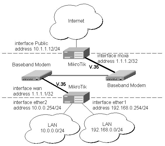
Let us consider the following network setup with two MikroTik Routers connected to a leased line with baseband modems:
The driver for MOXA C101 card should be loaded and the interface should be enabled according to the instructions given above. The IP addresses assigned to the synchronous interface should be as follows:
[MikroTik] ip address> add address 1.1.1.1/32 interface wan \
network 1.1.1.2 broadcast 255.255.255.255
[MikroTik] ip address> print
  # ADDRESS         NETMASK         NETWORK         BROADCAST       INTERFACE
  0 10.0.0.254      255.255.255.0   10.0.0.254      10.0.0.255      ether2
  1 192.168.0.254   255.255.255.0   192.168.0.254   192.168.0.255   ether1
  2 1.1.1.1         255.255.255.255 1.1.1.2         255.255.255.255 wan
[MikroTik] ip address> /ping 1.1.1.2
1.1.1.2 pong: ttl=255 time=27 ms
1.1.1.2 pong: ttl=255 time=27 ms
1.1.1.2 pong: ttl=255 time=27 ms
3 packets transmitted, 3 packets received, 0% packet loss
round-trip min/avg/max = 27/27.0/27 ms
[MikroTik] ip address>
Note, that for the point-to-point link the network mask is set to 32 bits, the argument 'network' is set to the IP address of the other end, and the broadcast address is set to 255.255.255.255. The default route should be set to the gateway router 1.1.1.2:
[MikroTik] ip route> add gateway 1.1.1.2 interface wan
[MikroTik] ip route> pr
  # DST-ADDRESS     NETMASK         GATEWAY         PREF-ADDRESS    INTE...
  0 10.0.0.0        255.255.255.0   0.0.0.0         10.0.0.254      ether2  D K
  1 192.168.0.0     255.255.255.0   0.0.0.0         192.168.0.254   ether1  D K
  2 1.1.1.2         255.255.255.255 0.0.0.0         1.1.1.1         wan     D K
  3 0.0.0.0         0.0.0.0         1.1.1.2         0.0.0.0         wan
[MikroTik] ip route>
The configuration of the Mikrotik router at the other end is similar:
[MikroTik] ip address> add address 1.1.1.2/32 interface moxa \
network 1.1.1.1 broadcast 255.255.255.255
[MikroTik] ip address> print
  # ADDRESS         NETMASK         NETWORK         BROADCAST       INTERFACE
  0 10.1.1.12       255.255.255.0   10.1.1.12       10.1.1.255      Public
  1 1.1.1.2         255.255.255.255 1.1.1.1         255.255.255.255 moxa
[MikroTik] ip address> /ping 1.1.1.1
1.1.1.1 pong: ttl=255 time=27 ms
1.1.1.1 pong: ttl=255 time=27 ms
1.1.1.1 pong: ttl=255 time=27 ms
3 packets transmitted, 3 packets received, 0% packet loss
round-trip min/avg/max = 27/27.0/27 ms
[MikroTik] ip address>
MikroTik Router to CISCO Router
Let us consider the following network setup with MikroTik Router connected to a leased line with baseband modems and a CISCO router at the other end:
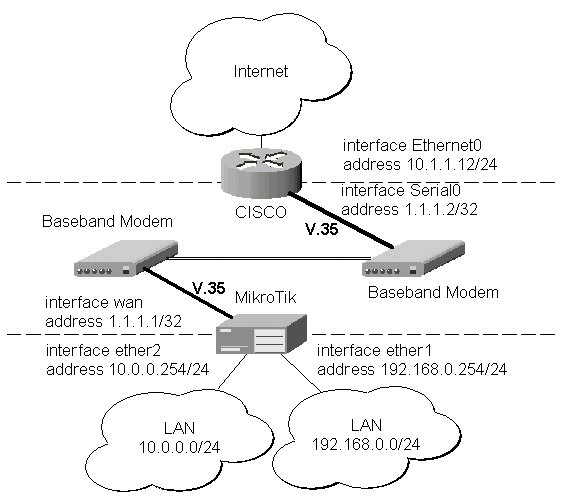
The driver for MOXA C101 card should be loaded and the interface should be enabled according to the instructions given above. The IP addresses assigned to the synchronous interface should be as follows:
[MikroTik] ip address> add address 1.1.1.1/32 interface wan \
network 1.1.1.2 broadcast 255.255.255.255
[MikroTik] ip address> print
  # ADDRESS         NETMASK         NETWORK         BROADCAST       INTERFACE
  0 10.0.0.254      255.255.255.0   10.0.0.254      10.0.0.255      ether2
  1 192.168.0.254   255.255.255.0   192.168.0.254   192.168.0.255   ether1
  2 1.1.1.1         255.255.255.255 1.1.1.2         255.255.255.255 wan
[MikroTik] ip address> /ping 1.1.1.2
1.1.1.2 pong: ttl=255 time=27 ms
1.1.1.2 pong: ttl=255 time=27 ms
1.1.1.2 pong: ttl=255 time=27 ms
3 packets transmitted, 3 packets received, 0% packet loss
round-trip min/avg/max = 27/27.0/27 ms
[MikroTik] ip address>
Note, that for the point-to-point link the network mask is set to 32 bits, the argument 'network' is set to the IP address of the other end, and the broadcast address is set to 255.255.255.255. The default route should be set to the gateway router 1.1.1.2:
[MikroTik] ip route> add gateway 1.1.1.2 interface wan
[MikroTik] ip route> pr
  # DST-ADDRESS     NETMASK         GATEWAY         PREF-ADDRESS    INTE...
  0 10.0.0.0        255.255.255.0   0.0.0.0         10.0.0.254      ether2  D K
  1 192.168.0.0     255.255.255.0   0.0.0.0         192.168.0.254   ether1  D K
  2 1.1.1.2         255.255.255.255 0.0.0.0         1.1.1.1         wan     D K
  3 0.0.0.0         0.0.0.0         1.1.1.2         0.0.0.0         wan
[MikroTik] ip route>
The configuration of the CISCO router at the other end (part of the configuration) is:
CISCO#show running-config
Building configuration...

Current configuration:
...
!
interface Ethernet0
 description connected to EthernetLAN
 ip address 10.1.1.12 255.255.255.0
!
interface Serial0
 description connected to MikroTik
 ip address 1.1.1.2 255.255.255.252
 serial restart-delay 1
!
ip classless
ip route 0.0.0.0 0.0.0.0 10.1.1.254
!
...
end

CISCO#
Send ping packets to the MikroTik router:
CISCO#ping 1.1.1.1

Type escape sequence to abort.
Sending 5, 100-byte ICMP Echos to 1.1.1.1, timeout is 2 seconds:
!!!!!
Success rate is 100 percent (5/5), round-trip min/avg/max = 28/32/40 ms
CISCO#