CISCO/Aironet 2.4GHz 11Mbps Wireless Interface

Document revision 1.3 (11-Jun-2003)
This document applies to the MikroTik RouterOS V2.7

Table of Contents

Summary

The MikroTik RouterOS supports the following CISCO/Aironet 2.4GHz Wireless ISA/PCI/PC Adapter hardware:

Specifications

Packages required : wireless
License required : 2.4GHz Wireless Client
Home menu level : /interface pc
Protocols utilized : IEEE802.11b (IEEE802.11b)
Hardware usage : not significant

Related Documents

Software Package Installation and Upgrading
Device Driver Management
IP Addresses and Address Resolution Protocol (ARP)
Log Management
Notes on PCMCIA Adapters

Wireless Interface Configuration

Submenu level : /interface pc

Description

CISCO/Aironet 2.4GHz card is an interface for wireless networks operating in IEEE 802.11b standard. If the wireless interface card is not registered to an AP, the green status led is blinking fast. If the wireless interface card is registered to an AP, the green status led is blinking slow. To set the wireless interface for working with an access point (register to the AP), typically you should set the following parameters:

Property Description

name (name) - assigned interface name
mtu (integer: 0..65536, default: 1500) - Maximum Transmission Unit
mode (infrastructure | ad-hoc, default: infrastructure) - operation mode of the card
rts-threshold (integer: 0..2312, default: 2312) - determines the packet size at which the interface issues a request to send (RTS) before sending the packet. A low value can be useful in areas where many clients are associating with the access point or bridge, or in areas where the clients are far apart and can detect only the access point or bridge and not each other
fragmentation-threshold (integer: 256..2312, default: 2312) - this threshold controls the packet size at which outgoing packets will be split into multiple fragments. If a single fragment transmit error occurs, only that fragment will have to be retransmitted instead of the whole packet. Use a low setting in areas with poor communication or with a great deal of radio interference
tx-power (1 | 5 | 20 | 50 | 100, default: 100) - transmit power in mW
rx-antenna (both | default | left | right, default: both) - receive antennas
tx-antenna (both | default | left | right, default: both) - transmit antennas
long-retry-limit (integer: 0..128, default: 16) - specifies the number of times an unfragmented packet is retried before it is dropped
short-retry-limit (integer: 0..128, default :16) - specifies the number of times a fragmented packet is retried before it is dropped
frequency (default | 2412 | 2417 | 2422 | 2427 | 2432 | 2437 | 2442 | 2447 | 2452 | 2457 | 2462 | 2467 | 2472 | 2484MHz, default: 2437) - channel frequency in MHz
data-rate (11 | 1 | 2 | 5.5 | auto, default: 1) - data rate in Mbit/s
ap1 (MAC address) - forces association to the specified access point
ap2 (MAC address) - forces association to the specified access point
ap3 (MAC address) - forces association to the specified access point
ap4 (MAC address) - forces association to the specified access point
ssid1 (text, default: tsunami) - establishes the adapter's service set identifier This value must match the SSID of the system in order to operate in infrastructure mode
ssid2 (text, default: "") - service set identifier 2
ssid3 (text, default: "") - service set identifier 3
modulation (cck | default | mbok, default: cck) - modulation mode
client-name (text, default: "") - client name
join-net (time, default 10) - the time, during which the interface in ad-hoc mode will try to connect to a network rather then create a new one
  • 0 - do not create own network
  • beacon-period (integer, default: 100) - establishes a beaconing period
    arp (disabled | enabled | proxy-arp | reply-only, default: enabled) - Address Resolution Protocol
    card-type (read-only: card type) - your CISCO/Aironet adapter model and type

    Example

    [admin@MikroTik] > interface print
    Flags: X - disabled, D - dynamic, R - running
      #    NAME                 TYPE             MTU
      0  R ether1               ether            1500
      1  X ether2               ether            1500
      2  X pc1                  pc               1500
    [admin@MikroTik] interface> set 1 name aironet
    [admin@MikroTik] interface> enable aironet
    [admin@MikroTik] > interface print
    Flags: X - disabled, D - dynamic, R - running
      #    NAME                 TYPE             MTU
      0  R ether1               ether            1500
      1  X ether2               ether            1500
      2  R aironet              pc               1500
    [admin@MikroTik] > interface pc
    [admin@MikroTik] interface pc> print
    Flags: X - disabled, R - running
      0  R name="aironet" mtu=1500 mac-address=00:40:96:29:2F:80 arp=enabled
           client-name="" ssid1="tsunami" ssid2="" ssid3="" mode=infrastructure
           data-rate=1Mbit/s frequency=2437MHz modulation=cck tx-power=100
           ap1=00:00:00:00:00:00 ap2=00:00:00:00:00:00 ap3=00:00:00:00:00:00
           ap4=00:00:00:00:00:00 rx-antenna=right tx-antenna=right beacon-period=100
           long-retry-limit=16 short-retry-limit=16 rts-threshold=2312
           fragmentation-threshold=2312 join-net=10s card-type=PC4800A 3.65
    
    [admin@MikroTik] interface pc>
    
    You can monitor the status of the wireless interface:
    [admin@MikroTik] interface pc> monitor 0
             synchronized: no
               associated: no
             error-number: 0
    
    [admin@MikroTik] interface pc>
    
    Suppose we want to configure the wireless interface to accomplish registration on the AP with a ssid 'mt'. To do this, it is enough to change the argument value of ssid1 to mt:
    [admin@MikroTik] interface pc> set 0 ssid1 mt
    [admin@MikroTik] interface pc> monitor 0
             synchronized: yes
               associated: yes
                frequency: 2412MHz
                data-rate: 11Mbit/s
                     ssid: "mt"
             access-point: 00:02:6F:01:5D:FE
        access-point-name: ""
           signal-quality: 132
          signal-strength: -82
             error-number: 0
    
    [admin@MikroTik] interface pc>
    

    Troubleshooting

    Keep in mind, that not all combinations of I/O base addresses and IRQ's may work on particular motherboard. It is recommended that you choose an IRQ not used in your system, and then try to find an acceptable I/O base address setting. As it has been observed, the IRQ 5 and I/O 0x300 or 0x180 will work in most cases.

    Wireless Network Applications

    Two possible wireless network configurations are discussed in the following examples:
  • Point-to-Multipoint (Wireless Infrastructure)
  • Point-to-Point (Peer-to-Peer, or Ad-Hoc Wireless LAN)

    Point-to-Multipoint Wireless LAN

    Let us consider the following network setup with CISCO/Aironet Wireless Access Point as a base station and MikroTik Wireless Router as a client:

    Point-to-Multipoint

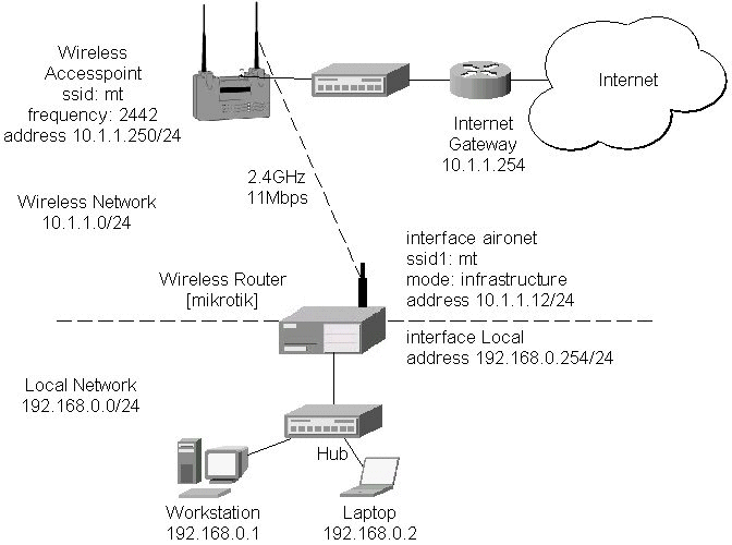
    The access point is connected to the wired network's HUB and has IP address from the network 10.1.1.0/24. The minimum configuration required for the AP is:

    1. Setting the Service Set Identifier (up to 32 alphanumeric characters). In our case we use ssid "mt".
    2. Setting the allowed data rates at 1-11Mbps, and the basic rate at 1Mbps.
    3. Choosing the frequency, in our case we use 2442MHz.
    4. (For CISCO/Aironet Bridges only) Set Configuration/Radio/Extended/Bridge/mode=access_point. If you leave it to 'bridge_only', it wont register clients.
    5. Setting the identity parameters Configuration/Ident: Inaddr, Inmask, and Gateway. These are required if you want to access the AP remotely using telnet or http.

    Reminder! Please note, that the AP is not a router! It has just one network address, and is just like any host on the network. It resembles a wireless-to-Ethernet HUB or bridge. The AP does not route the IP traffic! There is no need to set up the routing table under Configuration/Ident/Routing.

    The frequency argument does not have any meaning, since the frequency of the AP is used. The IP addresses assigned to the wireless interface should be from the network 10.1.1.0/24, e.g.:

    [admin@MikroTik] ip address> add address 10.1.1.12/24 interface aironet
    [admin@MikroTik] ip address> print
    Flags: X - disabled, I - invalid, D - dynamic
      #   ADDRESS            NETWORK         BROADCAST       INTERFACE
      0   10.1.1.12/24       10.1.1.0        10.1.1.255      aironet
      1   192.168.0.254/24   192.168.0.0     192.168.0.255   Local
    [admin@MikroTik] ip address>
    
    The default route should be set to the gateway router 10.1.1.254 (! not the AP 10.1.1.250 !):
    [admin@MikroTik] ip route> add gateway=10.1.1.254
    [admin@MikroTik] ip route> print
    Flags: X - disabled, I - invalid, D - dynamic, J - rejected,
    C - connect, S - static, R - rip, O - ospf, B - bgp
        #    DST-ADDRESS        G GATEWAY         DISTANCE INTERFACE
        0  S 0.0.0.0/0          r 10.1.1.254      1        aironet
        1 DC 192.168.0.0/24     r 0.0.0.0         0        Local
        2 DC 10.1.1.0/24        r 0.0.0.0         0        aironet
    [admin@MikroTik] ip route>
    

    Point-to-Point Wireless LAN

    Point-to-point connections using two wireless clients require the wireless cards to operate in ad-hoc mode. This mode does not provide the required timing for the cases of long distance (over 20km) links. Thus, the performance of such links is very poor on long distances, and use of infrastructure mode is required, where a wireless client registers to an access point or bridge.

    Let us consider the following point-to-point wireless network setup with two MikroTik wireless routers:

    Point-to-Point

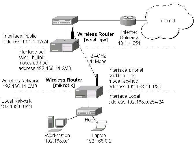
    To establish a point-to-point link, the configuration of the wireless interface should be as follows:

    The following command should be issued to change the settings for the pc interface of the master unit:

    [admin@MikroTik] interface pc> set 0 mode=ad-hoc ssid1=b_link frequency=2442MHz \
    \... bitrate=auto
    [admin@MikroTik] interface pc>
    

    For 10 seconds (this is set by the argument join-net) the wireless card will look for a network to join. The status of the card is not synchronized, and the green status light is blinking fast. If the card cannot find a network, it creates its own network. The status of the card becomes synchronized, and the green status led becomes solid. The monitor command shows the new status and the MAC address generated:

    [admin@MikroTik] interface pc> monitor 0
             synchronized: yes
               associated: yes
                frequency: 2442MHz
                data-rate: 11Mbit/s
                     ssid: "b_link"
             access-point: 2E:00:B8:01:98:01
        access-point-name: ""
           signal-quality: 35
          signal-strength: -62
             error-number: 0
    
    [admin@MikroTik] interface pc>
    
    The other router of the point-to-point link requires the operation mode set to ad-hoc, the System Service Identificator set to "b_link", and the channel frequency set to 2412MHz. If the radios are able to establish RF connection, the status of the card should become synchronized, and the green status led should become solid immediately after entering the command:
    [admin@wnet_gw] interface pc> set 0 mode=ad-hoc ssid1=b_link frequency=2412MHz \
    \... bitrate=auto
    [admin@wnet_gw] interface pc> monitor 0
             synchronized: yes
               associated: no
                frequency: 2442MHz
                data-rate: 11Mbit/s
                     ssid: "b_link"
             access-point: 2E:00:B8:01:98:01
        access-point-name: ""
           signal-quality: 131
          signal-strength: -83
             error-number: 0
    
    [admin@wnet_gw] interface pc>
    

    As we see, the MAC address under the access-point parameter is the same as generated on the first router.

    If desired, IP addresses can be assigned to the wireless interfaces of the pint-to-point linked routers using a smaller subnet, say 30-bit one:

    [admin@MikroTik] ip address> add address 192.168.11.1/30 interface aironet
    [admin@MikroTik] ip address> print
    Flags: X - disabled, I - invalid, D - dynamic
      #   ADDRESS            NETWORK         BROADCAST       INTERFACE
      0   192.168.11.1/30    192.168.11.0    192.168.11.3    aironet
      1   192.168.0.254/24   192.168.0.0     192.168.0.255   Local
    [admin@MikroTik] ip address>
    

    The second router will have address 192.168.11.2. The network connectivity can be tested by using ping or bandwidth test:

    [admin@wnet_gw] ip address> add address 192.168.11.2/30 interface aironet
    [admin@wnet_gw] ip address> print
    Flags: X - disabled, I - invalid, D - dynamic
      #   ADDRESS            NETWORK         BROADCAST       INTERFACE
      0   192.168.11.2/30    192.168.11.0    192.168.11.3    aironet
      1   10.1.1.12/24       10.1.1.0        10.1.1.255      Public
    [admin@wnet_gw] ip address> /ping 192.168.11.1
    192.168.11.1 pong: ttl=255 time=3 ms
    192.168.11.1 pong: ttl=255 time=1 ms
    192.168.11.1 pong: ttl=255 time=1 ms
    192.168.11.1 pong: ttl=255 ping interrupted
    4 packets transmitted, 4 packets received, 0% packet loss
    round-trip min/avg/max = 1/1.5/3 ms
    [admin@wnet_gw] interface pc> /tool bandwidth-test 192.168.11.1 protocol tcp
                      status: running
                  rx-current: 4.61Mbps
        rx-10-second-average: 4.25Mbps
            rx-total-average: 4.27Mbps
    
    [admin@wnet_gw] interface pc> /tool bandwidth-test 192.168.11.1 protocol udp size 1500
                      status: running
                  rx-current: 5.64Mbps
        rx-10-second-average: 5.32Mbps
            rx-total-average: 4.87Mbps
    
    [admin@wnet_gw] interface pc>


    Additional Resources

    www.aironet.com
    www.cisco.com/warp/public/44/jump/wireless.shtml
    Cisco - Cisco Aironet 350 Series
    For more information about the CISCO/Aironet PCI/ISA adapter hardware please see the relevant User’s Guides and Technical Reference Manuals in pdf format:

    Documentation about CISCO/Aironet Wireless Bridges and Access Points can be found in archives:


    © Copyright 1999-2002, MikroTik